
Electromagnetic relay

Active Publication Date: 2005-12-01
EM DEVICES CORP
View PDF4 Cites 12 Cited by
  • Summary
  • Abstract
  • Description
  • Claims
  • Application Information

AI Technical Summary

Benefits of technology

[0010] In view of the above, it is an object of the present invention to provide an electromagnetic relay which is small in size and is capable of controlling two circuits each having one ordinarily-open contact and of having a large current-carrying capacity and high interrupting capability and being excellent in resistance against shock and vibration.

Problems solved by technology

However, conventionally, a single electro-magnetic relay has not yet been known which has a current-carrying capability (which allows a current of, for example, 100A to flow) and an interrupting capability (which can interrupt a voltage and a current of, for example, 100A at 14V) being large enough for one electromagnetic relay to be able to control one three-phase brushless motor for electric power steering.
When a plurality of electromagnetic relays each having only one circuit with one ordinarily-open contact is used for the control of the three-phase brushless motor, a ratio of the electromagnetic relays to occupy a space within a device using electrical and electronic components becomes greater, use of a plurality of electromagnetic relays does not meet a customer demand to provide a space-saving structure as much as possible for the devices made up of electrical and electronic components.

Method used


Image

  • Electromagnetic relay
  • Electromagnetic relay
  • Electromagnetic relay

Examples


Embodiment Construction

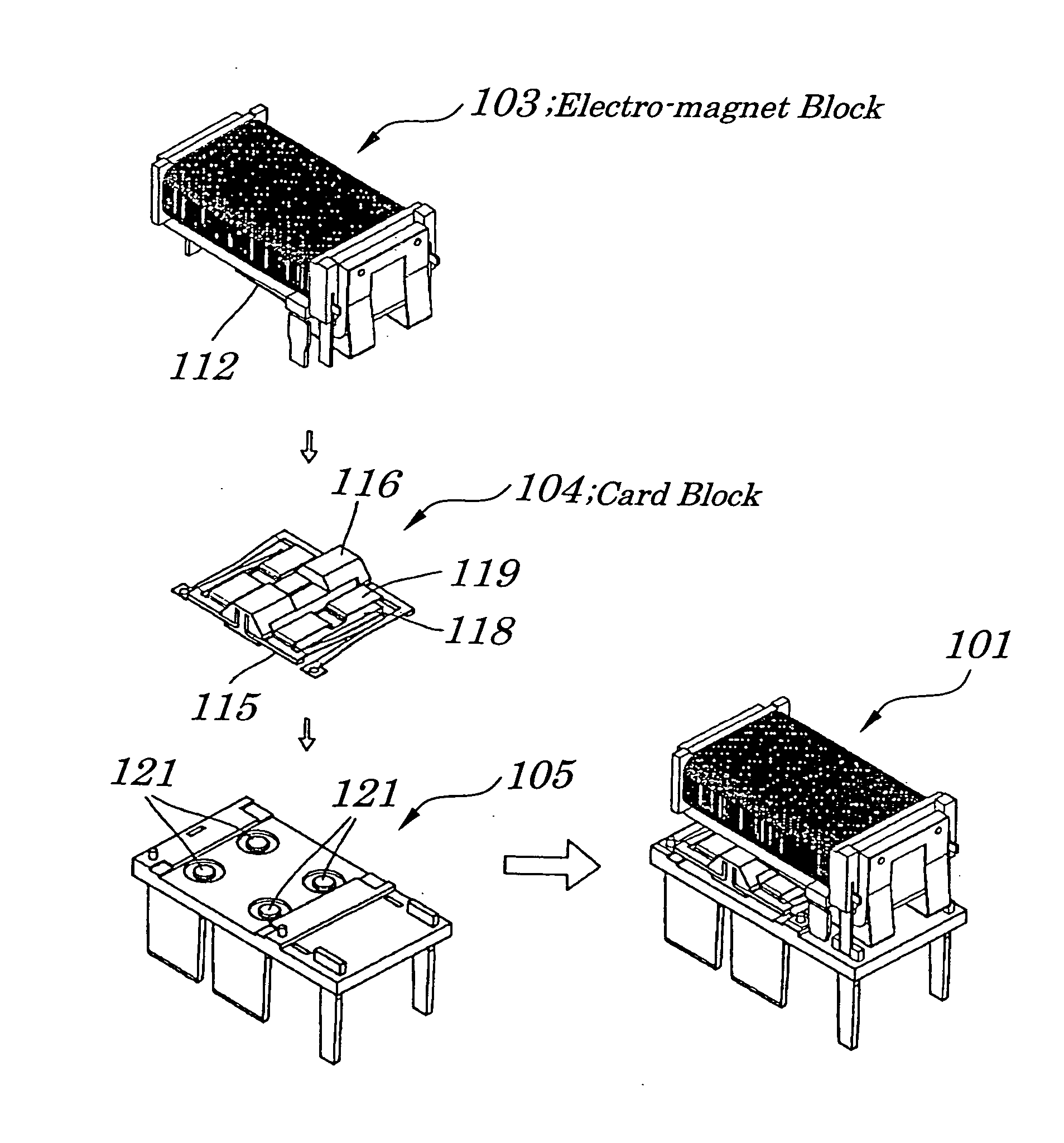
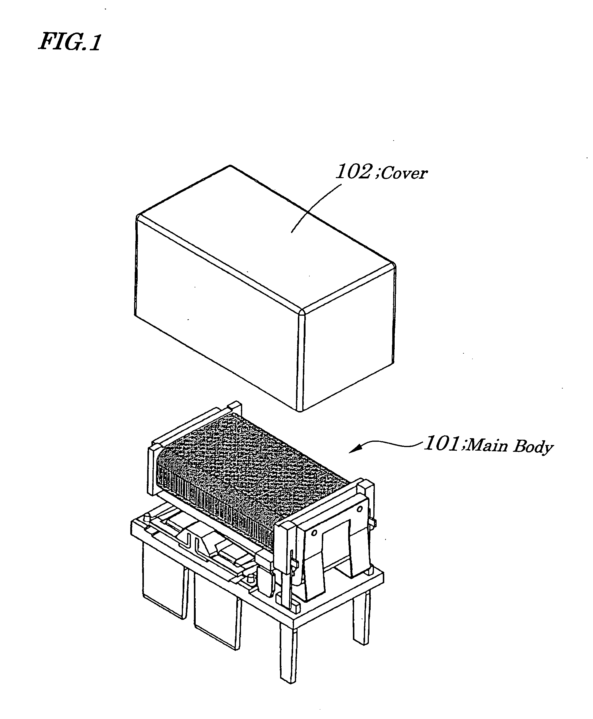
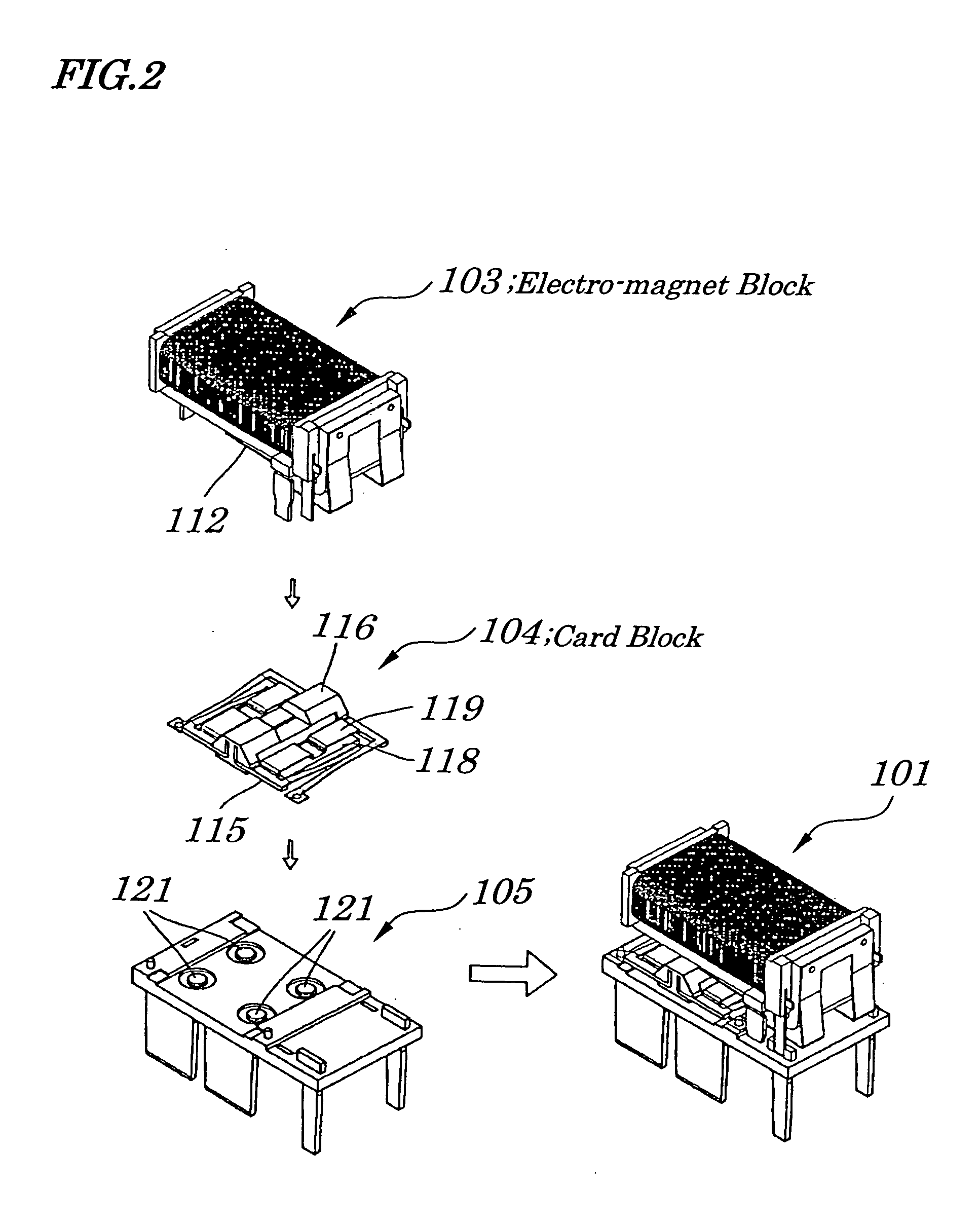
[0047] Best modes of carrying out the present invention will be described in further detail using various embodiments with reference to the accompanying drawings. FIG. 1 is a perspective view of an electromagnetic relay according to a preferable embodiment of the present invention. FIG. 2 is an exploded perspective view of a main body 101 of the electromagnetic relay according to the same embodiment. FIG. 3 is an exploded perspective view of an electro-magnet block 103 according to the same embodiment. FIG. 4 is an exploded perspective view of a card block 104 according to the same embodiment. FIG. 5 is an exploded perspective view of a base block 105 according to the same embodiment. FIG. 6 is a diagram illustrating a circuit and terminals of the electromagnetic relay. In FIG. 6, terminals 161 and 166 are connected to a coil, terminals 162 and 165 are connected to a first ordinarily-open contact, and terminals 163 and 164 are connected to a second ordinarily-open contact.

[0048] As...


PUM


Abstract

An electromagnetic relay is provided which is small in size and is capable of controlling two circuits of an ordinarily-open contact, which has a large current-carrying capacity and high interrupting capability, and which is excellent in resistance against shock and vibration. Movable contactors are held, through bow-shaped movable contactor springs, to two -shaped holding frames each being electrically separated and being mechanically connected via a card made of a highly heat-resistant resin in a card block. Thick-plate shaped movable contacts, which are attached to the movable contactors in a fixed manner, are electrically connected or disconnected to fixed contacts in a base block, in synchronization with operations of an armature of an electro-magnet block. In order to improve a current-carrying capability and interrupting capability, there are provided two pieces of ordinarily-open contacts which are connected in series to each other, and between which an interval is doubled, in each of two circuits.

Description

BACKGROUND OF THE INVENTION [0001] 1. Field of the Invention [0002] The present invention relates to an electromagnetic relay and more particularly to the electromagnetic relay being suitable for control of a vehicle-mounted three-phase brushless motor. [0003] The present application claims priority of Japanese Patent Application No. 2004-158951 filed on May 28, 2004, which is hereby incorporated by reference. [0004] 2. Description of the Related Art [0005] In recent years, an operating method of power steering for an automobile is changing from a hydraulic type to an electric type with the aim of improving automobile fuel consumption. At present a steering method for controlling a DC (Direct Current) motor is used in electric power steering systems in most cases. However, electric power steering systems using a three-phase brushless motor increases as its application of electric power steering to an automobile having a large piston displacement increases. As a result, a switching d...

Claims


Application Information

Patent Timeline
IPC IPC(8): H01H50/04H01H50/56H01H50/26H01H50/54H01H50/64
CPCH01H50/546
Inventor CHIDA, YOSHIFUMICHIBA, KEIIDE, TATSUMIKASAI, SHIGERU
Owner EM DEVICES CORP
Learn More