
Test board locking device including stiffener

Inactive Publication Date: 2005-12-01
SAMSUNG ELECTRONICS CO LTD
View PDF3 Cites 3 Cited by
  • Summary
  • Abstract
  • Description
  • Claims
  • Application Information

AI Technical Summary

Benefits of technology

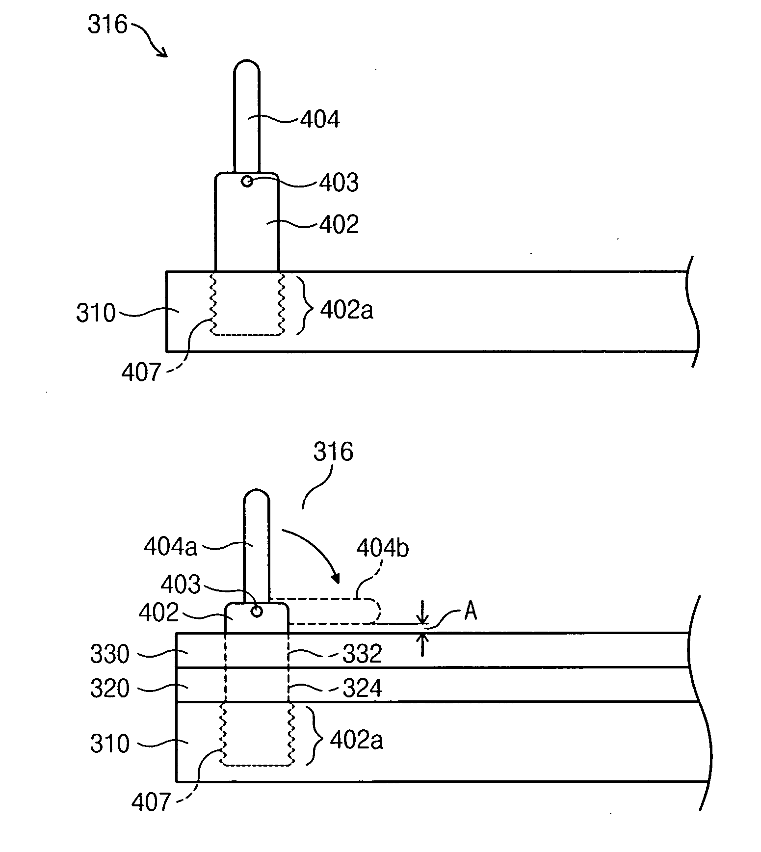
[0013] The present invention is directed to a test board locking device for readily removing and attaching a test board mounted to a test device for testing a semiconductor chip.
[0016] In one embodiment, the fix bars are coupled to the stiffener at a threaded interface. Each of the fix bars has a base with a male thread that mates with a female hole formed in the stiffener. Adjustment of the height of the fix bars by raising and lowering them allows for secure locking of test boards of varying thicknesses.

Problems solved by technology

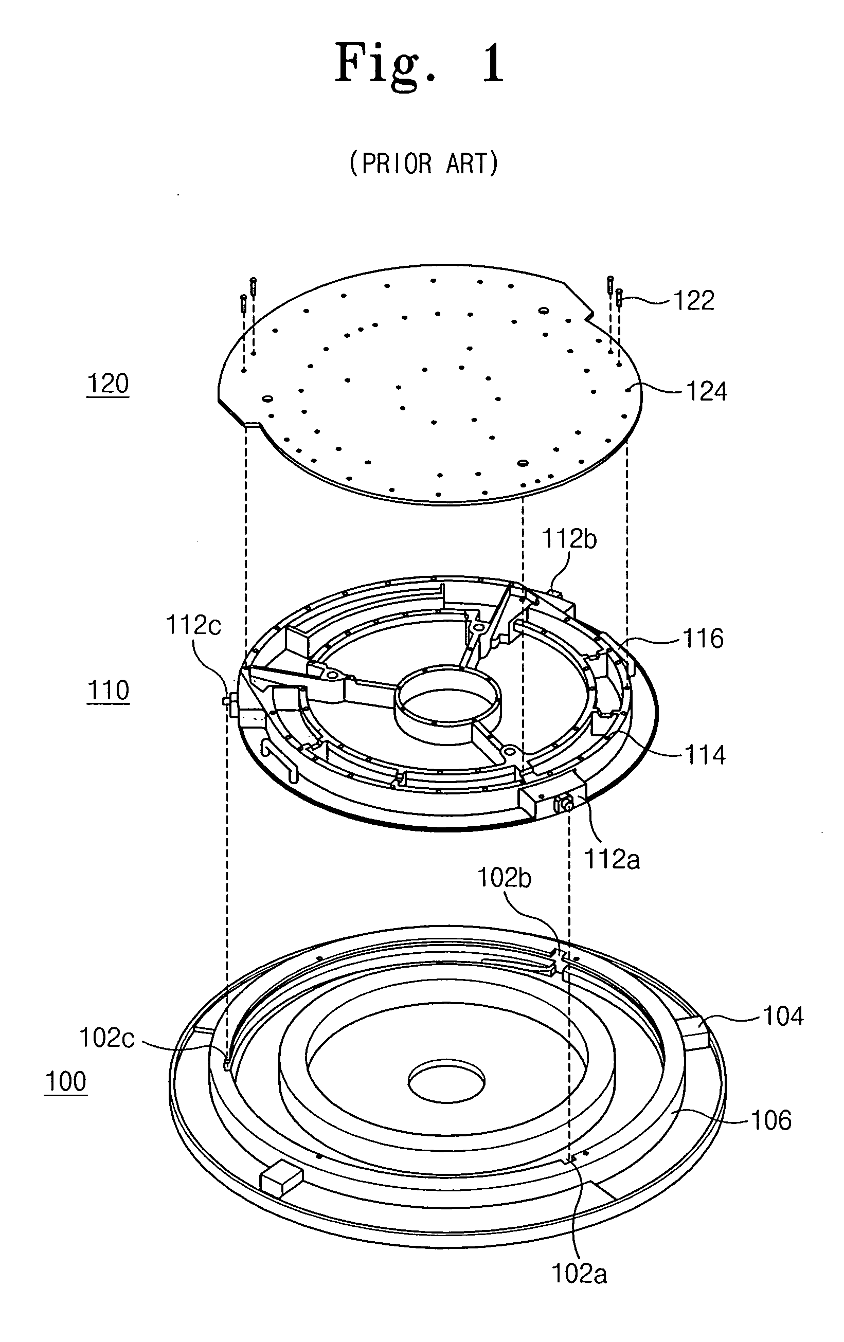
For this reason, this test board replacement process has a negative impact on processing efficiency.
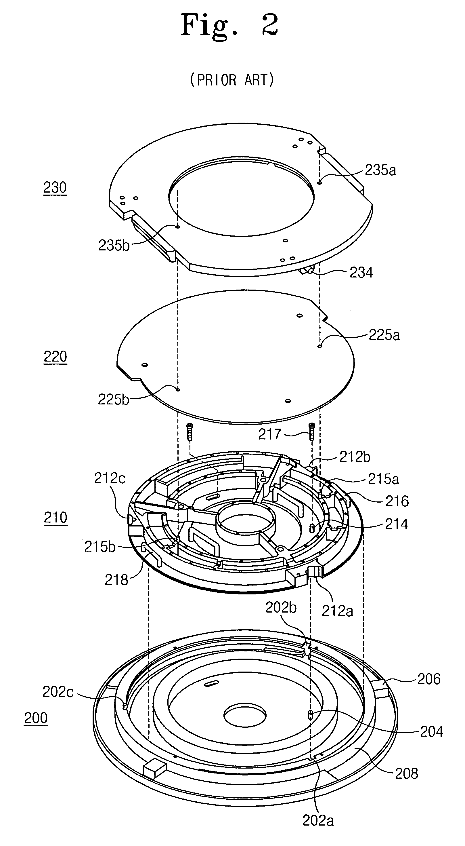
Nevertheless, the configuration of FIG. 2 still requires manual performance of screwing and unscrewing operations and the unit is relatively complex in structure.

Method used


Image

  • Test board locking device including stiffener
  • Test board locking device including stiffener
  • Test board locking device including stiffener

Examples


Embodiment Construction

[0029] As illustrated in FIG. 3, a test board locking device according to the present invention comprises a mounting unit 300, a stiffener 310, a test board 320, and a lid 330.

[0030] The mounting unit 300 is included in a test head of a test apparatus and has a first lower part 301, a rotatable bowl 304, a plurality of control bars 306, and three guide grooves 302a, 302b, and 302c. The rotatable bowl 304 is disposed on the first lower part 301 and is rotatable at a predetermined angle. The control bars 306 are protrudingly attached to an outer lateral face of the rotatable bowl 304 to readily handle a rotation of the rotatable bowl 304. The three guide grooves 302a, 302b, and 302c are formed on a top surface of the rotatable bowl 304 in regular intervals. Each of the grooves 302a, 302b, and 302c is connected to a furrow formed on an inner lateral face of the rotatable bowl 304.

[0031] The stiffener 310 has a second lower part 312 and an inner ring 313. The second lower part 312 has...


PUM


Abstract

A test board locking device includes a stiffener having a plurality of spaced-apart fix bars. A test board has first fix holes each corresponding to the fix bars adapted for coupling to the stiffener. A lid has second fix holes each corresponding to the fix bars, the lid adapted for coupling the test board to the stiffener. The fix bars extend from the stiffener and are coupled to the stiffener such that rotation of each fix bar in a first direction causes the fix bar to be raised relative to the stiffener and rotation of each fix bar in a second direction causes the fix bar to be lowered relative to the stiffener.

Description

RELATED APPLICATIONS [0001] This application claims priority to Korean Patent Application No. 2004-39025, filed on May 31, 2004 in the Korean Intellectual Property Office, the disclosure of which is incorporated herein in its entirety by reference. BACKGROUND OF THE INVENTION [0002] 1. Field of the Invention [0003] The present invention relates to a test board locking device for test of semiconductor chips and, more particularly, to a test board locking device which is readily removable / attachable from / to a stiffener in an electrical die sorting (EDS) process during the formation of semiconductor chips. [0004] 2. Description of Related Art [0005] Semiconductor chips formed on a wafer using multiple semiconductor processes are assembled in a package that may be made of various materials and have various shapes. In an electrical die sorting (EDS) process, an electrical signal is applied to each pad of an unassembled chip to test whether the chip is operable or inoperable. Since inoper...

Claims


Application Information

Patent Timeline
IPC IPC(8): G01R31/02H01L21/66G01R31/28
CPCG01R31/2886G01R31/2863G01R31/2884G01R31/2887
Inventor JUN, SEUNG-HOON
Owner SAMSUNG ELECTRONICS CO LTD
Learn More