
Focus adjuster for laser beam machine

a laser beam machine and focus adjustment technology, applied in metal-working equipment, welding equipment, manufacturing tools, etc., can solve the problems of contaminated machining lenses, degradation of machining quality, etc., and achieve the effect of improving machining quality

Active Publication Date: 2005-12-01
YAMAZAKI MAZAK KK
View PDF17 Cites 8 Cited by
  • Summary
  • Abstract
  • Description
  • Claims
  • Application Information

AI Technical Summary

Benefits of technology

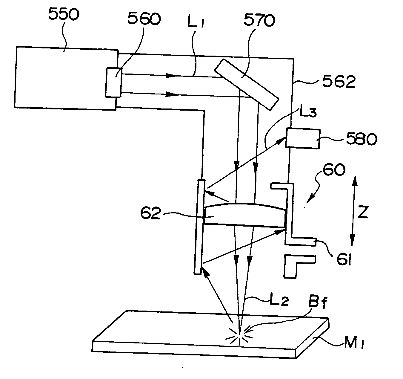
The present invention provides a focus adjuster for a laser beam machine to solve the problem of contamination on the machining lens. The machine includes a bed, a pallet, a column, a saddle, a machining head, a laser oscillator device, an output mirror, a mirror, an optical path system, and a reflection detector. The focus adjuster compensates for contamination by detecting reflected light and adjusting the focal position of the laser. This results in improved machining quality and allows for long, unattended operation without machining defects.

Problems solved by technology

The focal position of the machining lens set in this way is not always constant, but varies due to contamination or the like of the machining lens, causing a deviation between standard focal position and optimum focal position and resulting in machining defects such as degradation of machining quality.
Consequently, the machining lens gets contaminated, being open to the air in the factory.

Method used


Image

  • Focus adjuster for laser beam machine
  • Focus adjuster for laser beam machine
  • Focus adjuster for laser beam machine

Examples


Embodiment Construction

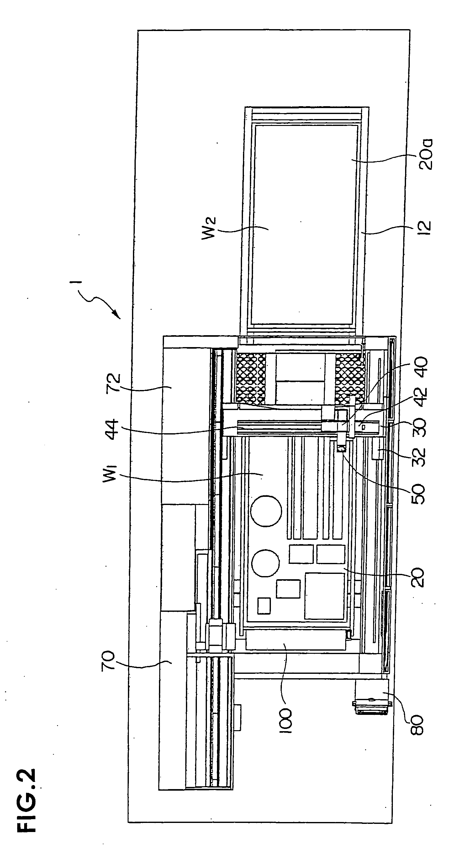
[0026]FIG. 1 is a perspective view showing an overall configuration of a laser beam machine according to the present invention, FIG. 2 is a plan view, FIG. 3 is a front view, FIG. 4 is a perspective view of the relevant portion; and FIG. 5 is a side view.

[0027] A laser beam machine, generally denoted by reference number 1, has a pallet (table) 20 which is disposed on a bed 10 to carry a plate-shaped workpiece W1. A pallet changer 12 is placed on the longitudinal extension of the bed 10, and a pallet 20a carrying a workpiece W2 to be machined next is awaiting its turn.

[0028] A pair of guide rails 34 are installed on both sides of the bed 10 along its length and a column 30 is mounted on the guide rails 34 in such a way as to be movable along an X axis.

[0029] Means for driving the column 30 along the X axis is provided by, for example, a linear motor, which is formed by a stator installed on the guide rails 34 and a moving member installed on a linear-motion guide 32.

[0030] A guid...


PUM

PropertyMeasurementUnit
thicknessaaaaaaaaaa
poweraaaaaaaaaa
reflection detectoraaaaaaaaaa

Abstract

The invention provides a focus adjuster for laser beam machine which adjusts focus by detecting reflected light of a laser beam in a laser beam machine. A laser beam outputted from a laser oscillator device 550 is reflected by a mirror 570 via an output mirror 560 and introduced into a laser machining tool. The laser beam collected by a machining lens 62 is reflected by a reflector plate M1 and sensed by a reflection detector 580. Automatic focus adjustment is achieved by sensing output of the reflected light as well as changes in focal position due to contamination of the machining lens 62.

Description

[0001] The present application is based on and claims priority of Japanese patent application No. 2004-156131 filed on May 26, 2004, the entire contents of which are hereby incorporated by reference. BACKGROUND OF THE INVENTION [0002] 1. Field of the Invention [0003] The present invention relates to a focus adjuster which prevents machining defects caused by changes in focal position of a machining lens due to contamination of the machining lens in order to make it possible to use unskilled operators in operating a laser beam machine, maximize quality and productivity for each material and workpiece thickness, and accomplish long, unattended operation under optimum machining conditions. [0004] 2. Description of the Related Art [0005] Conventionally, focal position of a laser beam narrowed by a machining lens is set beforehand in the thickness direction of a workpiece (e.g., along a Z axis). To set the focal position of the machining lens, a laser beam of appropriate power is emitted...

Claims


Application Information

Patent Timeline
Patent Type & Authority Applications(United States)
IPC IPC(8): B23K26/00B23K26/046B23K26/08
CPCB23K26/04B23K26/1482B23K26/0884B23K26/046
Inventor YAMAZAKI, TSUNEHIKOMIYAKAWA, NAOOMI
Owner YAMAZAKI MAZAK KK
Learn More