
Rate shaper algorithm

a rate shaper and algorithm technology, applied in the field of rate shapers, can solve the problems of high priority packets such as packets of real-time applications, too much for real-time applications, and special serious problems, and achieve the effects of reducing delay, reducing delay, and speeding up packet delivery

Inactive Publication Date: 2005-11-17
NOKIA CORP
View PDF8 Cites 51 Cited by
  • Summary
  • Abstract
  • Description
  • Claims
  • Application Information

AI Technical Summary

Benefits of technology

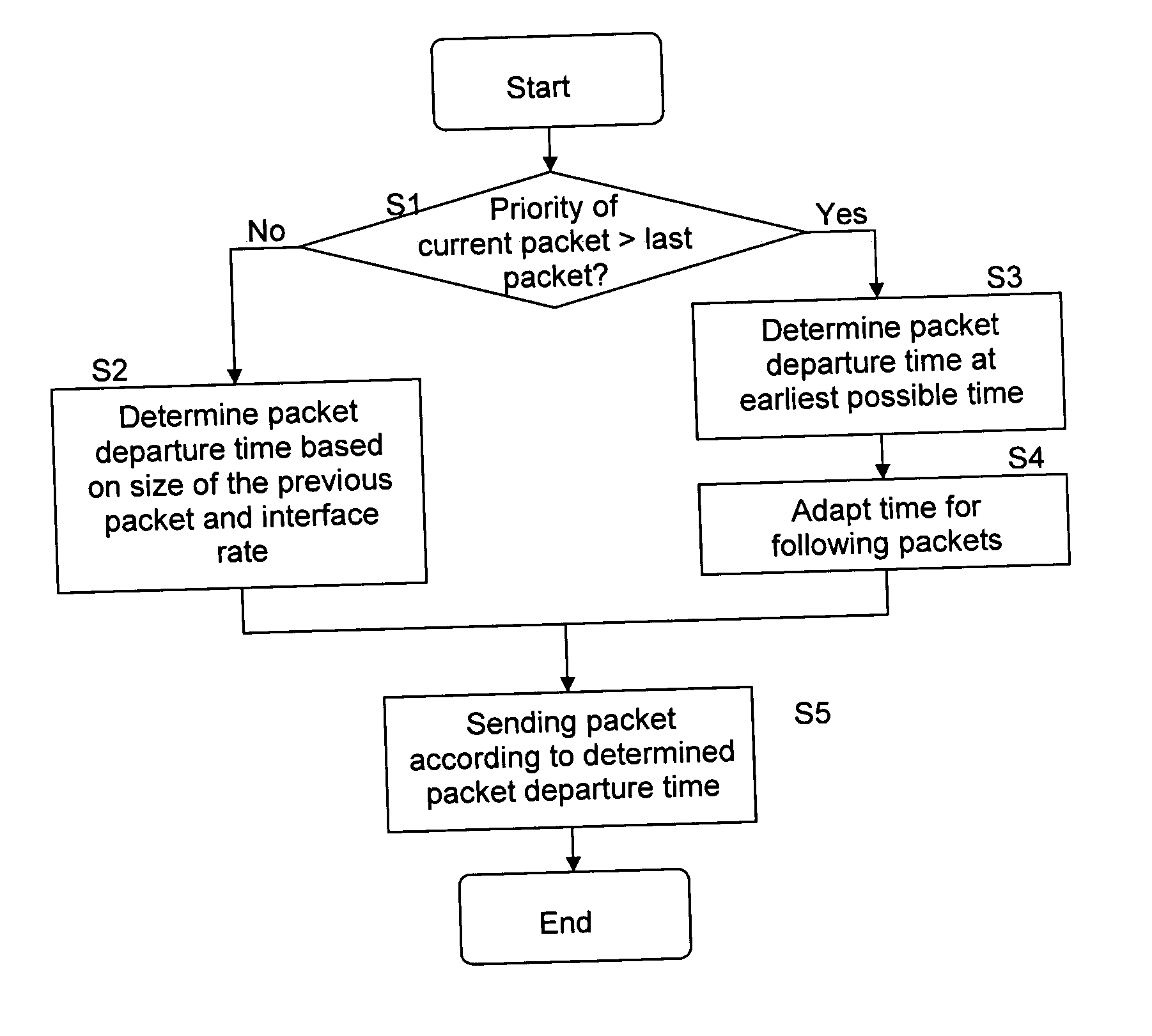
[0015] Hence, a faster delivery of packets having a higher priority is ensured.
[0017] Moreover, the algorithm according to the present invention is especially beneficial to minimise the delay of high priority, delay sensitive packets on low capacity links. Namely, on low capacity links the overall transmission time for big packets is long. If the algorithm is not used, a big low priority packet might occupy the transmission link for a long time thus leading to long delays for high priority, delay sensitive packets waiting for transmission.

Problems solved by technology

For example, the transmission of a 1500 Byte packet on an E1 link takes roughly 6 ms, during which the link is not available for other packets of possibly higher priority; this may be too much for real-time applications.
Thus, there is a problem that packets with high priorities such as packets of real-time applications may be delayed.
This problem is in particular serious when a rate shaper is applied which adjust the data rate of a data stream consisting of packets by inserting time gaps between subsequent packets according to the desired data rate.
In this situation, waiting the calculated time until the gap is over before transmitting the high priority packet will delay the high priority packet unnecessary long (maybe even too much), especially for low capacity layer 2 functions where the calculated gap can be long for big packets.
That is, the prioritised transmission of high priority packets by the layer 2 function cannot be sufficiently supported and, hence, the benefit of such a mechanism can not be exploited.

Method used


Image

  • Rate shaper algorithm
  • Rate shaper algorithm
  • Rate shaper algorithm

Examples


Embodiment Construction

[0025] In the following, a preferred embodiment of the present invention is described by referring to the attached drawings.

[0026] First, the general problem underlying the present invention is described in detail in the following.

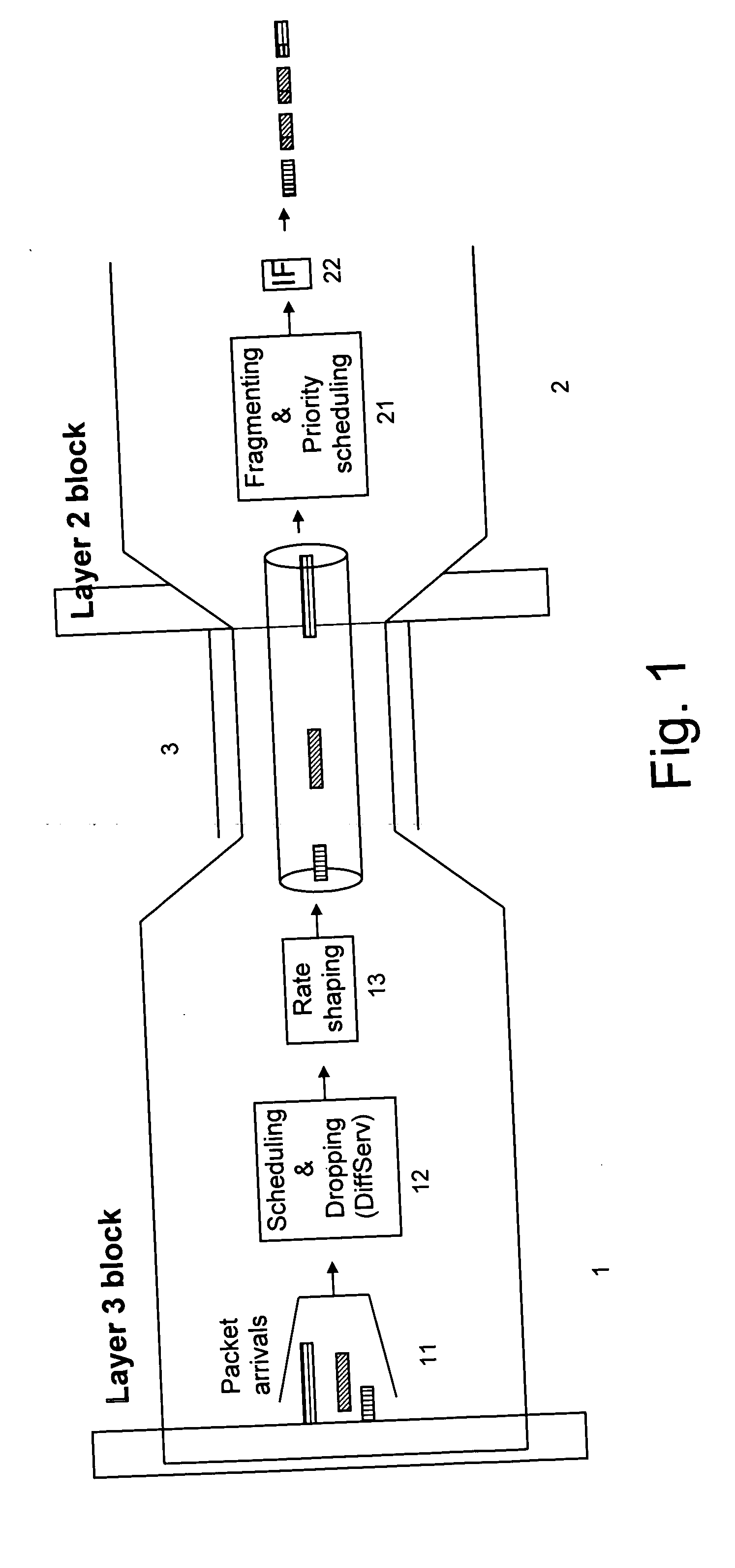
[0027] An IP router or MPLS label switching router may implement QoS mechanisms on layer 3 (e.g. following the Differentiated Services (Diffserv) architecture) as well as on layer 2 (e.g. MCMP or Diff-UBR). DiffServ on layer 3 works on complete packets and consists of packet scheduling according to priorities and potentially dropping for congestion avoidance. Various algorithms for strict priority scheduling, weighted scheduling and congestion avoidance are in use.

[0028] MCMP and Diff-UBR on layer 2 perform fragmentation of layer 3 packets in layer 2 fragments or cells and consist of fragment scheduling according to priorities. Also here, strict priority scheduling or a weighted scheduling mechanism can be applied. The purpose is to interleave fragments...


PUM


Abstract

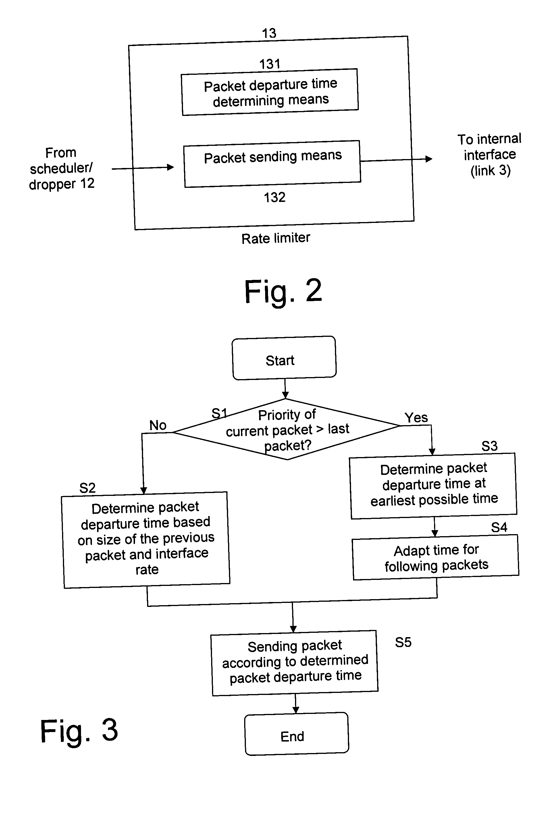
The invention proposes a rate shaping device, comprising a packet timing determining means (131) for determining departure times of packets to be sent, and a packet sending means (132) for sending the packets according to the determined departure times, wherein the packet timing determining means is adapted to determine the departure times by taking into account a desired data rate and a priority of the packets. The invention also proposes a corresponding method and a network system in which in a second network element the packets are fragmented according to the priority.

Description

BACKGROUND OF THE INVENTION [0001] 1. Field of the Invention [0002] The invention relates to a rate shaping device, a corresponding method and a network system comprising a rate shaping device and a packet fragmentation device. [0003] 2. Description of the Related Art [0004] Today's packet-oriented networks are required to provide service differentiation for applications with different Quality of Service (QoS) needs. Packet-oriented networks in this context are IP (Internet Protocol) and MPLS (Multiprotocol Label Switching) networks, for example. IP and MPLS are in the present description referred to as “Layer 3”, as only the packet-oriented nature of these protocols is of interest. QoS mechanisms on layer 3 (like DiffServ (Differentiated Services)) involve prioritization and dropping of packets, in order to achieve the desired behavior in terms of QoS parameters like delay, delay variation and loss. [0005] To further reduce delay and delay variation for high priority (urgent) packe...

Claims


Application Information

Patent Timeline
IPC IPC(8): H04L12/56H04L29/08
CPCH04L47/10H04L47/22H04L69/32H04L47/245H04L47/2408H04L47/43H04L69/325H04L69/324
Inventor BERGHOFF, GERALD
Owner NOKIA CORP
Learn More