Dual tuner
- Summary
- Abstract
- Description
- Claims
- Application Information
AI Technical Summary
Benefits of technology
Problems solved by technology
Method used
Image
Examples
first embodiment
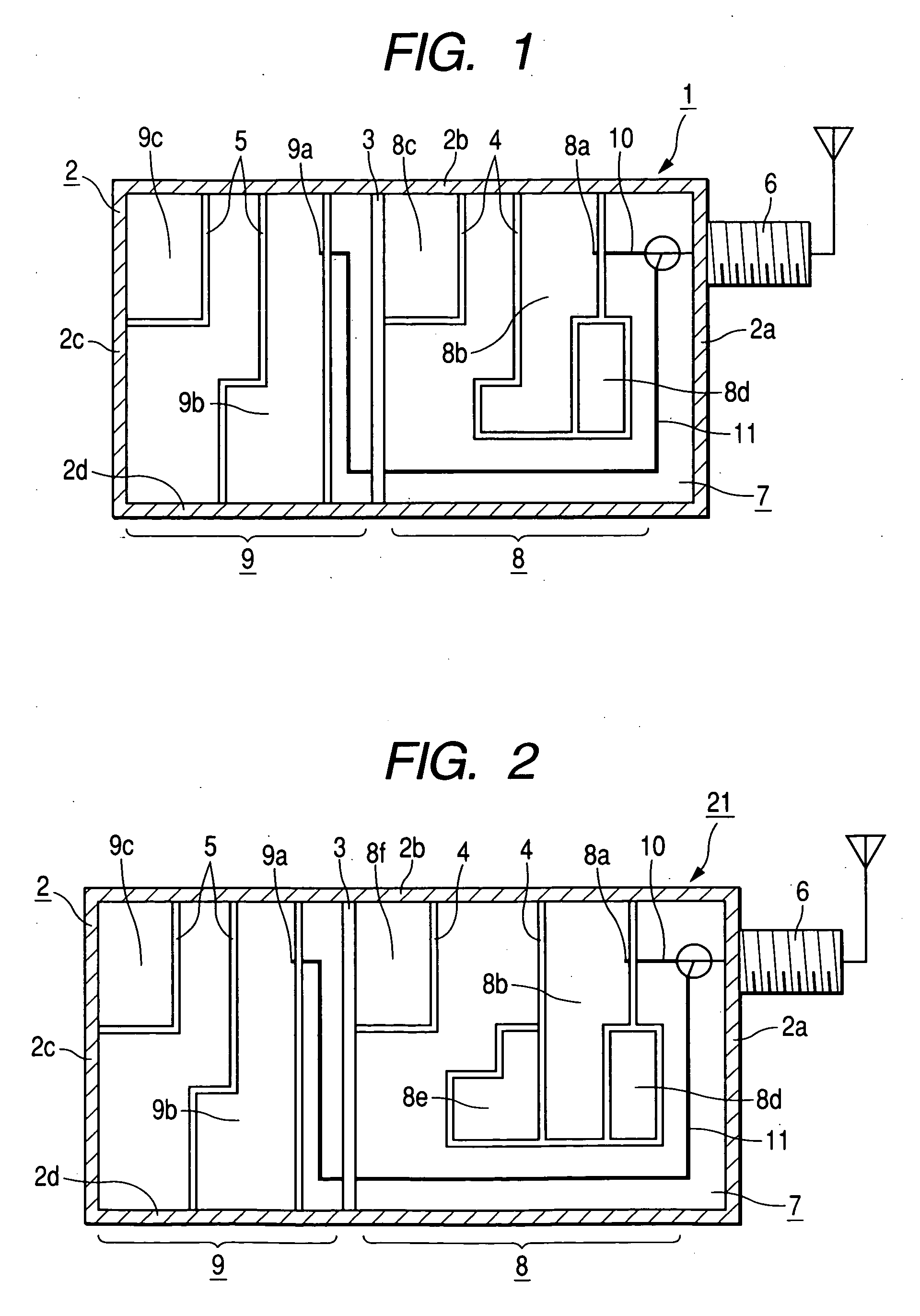
[0017] Preferred embodiments of the present invention will now be described with reference to the drawings. FIG. 1 is an explanatory view schematically illustrating a circuit layout of a dual tuner according to the present invention. The dual tuner 1 shown in FIG. 1 is accommodated in a setup box not shown in the drawings to be connected to a cable circuit in a CATV system, and operates as a tuner serving as a cable modem and a cable television receiver.
[0018] The dual tuner 1 mainly includes a rectangular parallelepiped casing 2 having four side plates 2a, 2b, 2c, 2d, partitions 3, 4, 5 for dividing inside of the casing 2 into a plurality of areas, a coaxial connector 6 fitted to one side plate 2a of the casing 2, and a circuit board 7 mounted in the casing 2, a data tuner 8 for a cable modem and a video tuner 9 for receiving cable television signals are mounted on a circuit board 7.
[0019] The casing 2 is made of a metallic plate, and has a chassis portion which is formed in a box...
second embodiment
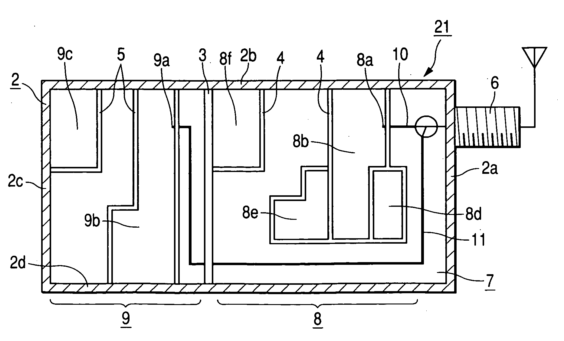
[0023]FIG. 2 is an explanatory view schematically illustrating a circuit layout of a dual tuner according to the present invention, the parts corresponding to FIG. 1 will be designated by the same reference numerals, and detailed description thereof will be omitted.
[0024] The dual tuner 21 shown in FIG. 2 includes a first frequency conversion circuit unit 8e for converting the reception signal passing through the band pass filter 8b into a first intermediate frequency signal, a second frequency conversion circuit 8f for converting the first intermediate frequency signal into a second intermediate frequency signal. The difference between the dual tuner 21 and the dual tuner 1 according to the first embodiment as mentioned above is that the oscillating frequency of the local oscillation circuit provided in the first frequency conversion circuit 8e and the second frequency conversion circuit 8f is set out of a reception band. That is, the data tuner 8 of the dual tuner 21 according to ...
third embodiment
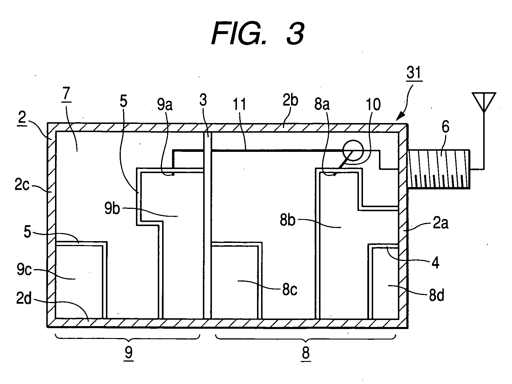
[0025]FIG. 3 is an explanatory view schematically illustrating a circuit layout of a dual tuner according to the present invention, the parts corresponding to FIG. 1 will be designated by the same reference numerals, and detailed description thereof will be omitted.
[0026] A difference between a dual tuner 31 shown in FIG. 3 and the dual tuner 1 according to the first embodiment previously mentioned is that the dual tuner 31 has both the input terminal 8a of the data tuner 8 for a cable modem and the input terminal 9a of the video tuner 9 for receiving cable television signals which are arranged so as to face the side plate 2b of the casing 2, whereby the signal line 11 of the video tuner 9 can be shortened. More specifically, a circuit layout that both the input terminal 8a of the tuner 8 and the input terminal 9a of the tuner 9 face the same side plate 2b is employed, whereby the signal line 11 of the video tuner 9 is arranged in a relatively short route which does not bypass the d...
PUM
 Abstract
Description
Claims
Application Information
 - R&D
- Intellectual Property
- Life Sciences
- Materials
- Tech Scout
- Unparalleled Data Quality
- Higher Quality Content
- 60% Fewer Hallucinations
Browse by: Latest US Patents, China's latest patents, Technical Efficacy Thesaurus, Application Domain, Technology Topic, Popular Technical Reports.
© 2025 PatSnap. All rights reserved.Legal|Privacy policy|Modern Slavery Act Transparency Statement|Sitemap|About US| Contact US: help@patsnap.com


