
Data dependent color wall filters

Inactive Publication Date: 2005-11-10
GENERAL ELECTRIC CO
View PDF13 Cites 4 Cited by
  • Summary
  • Abstract
  • Description
  • Claims
  • Application Information

AI Technical Summary

Benefits of technology

[0015] Yet another embodiment relates to a method of imaging moving tissue using an ultrasound imaging system. This embodiment of the method comprises initializing at least one filter in a wall filter module in the ultrasound imaging system, the filter responsive to tissue movement and filtering input data to the wall filter module. This method further comprises discarding at least one transient signal and outputting data having reducing flash and suppressed clutter.

Problems solved by technology

One limitation associated with taking Doppler effect measurements of reflected ultrasound waves from blood is that the received echo signal typically contains a large component produced by the stationary or slow moving tissues (alternatively referred to as “clutter” and “color flash artifacts” respectively), whereas the blood reflects ultrasound waves very weakly.
However, the reflections produced by moving tissue due to cardiac or respiratory motion are frequency shifted and may completely overwhelm signals from the slowly flowing blood.
However, a problem may arise in applying wall filtering in low-flow-velocity imaging.
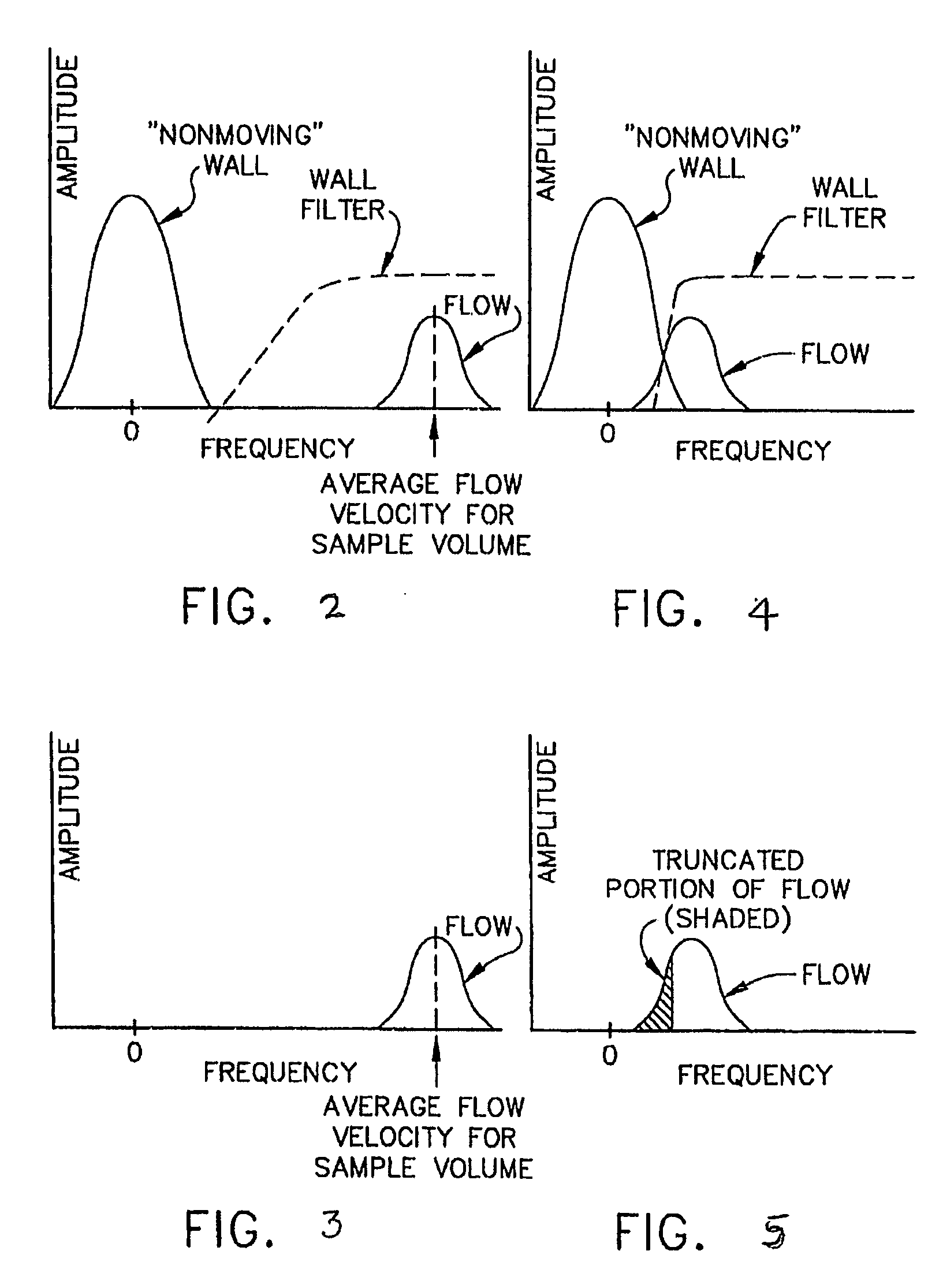
Since the frequencies of the non-moving wall and the slow-moving flow are close together, it is difficult to effectively apply a wall filter to eliminate the “wall” response without resulting in a distorted slow-flow response portion (see FIG. 2B).
Filtering in this way, however, may also remove signals from low-velocity blood flow, often the very signals that the operator wants to image.
As a result, the filter may work adequately at some locations in the field of view of the image, but not at other locations.
Therefore, the complex rotations may not insure that the output of the first stage or module of the bi-quad filter is close to zero.

Method used


Image

  • Data dependent color wall filters
  • Data dependent color wall filters
  • Data dependent color wall filters

Examples


Embodiment Construction

[0029] For the purpose of illustration only, the following detailed description references a certain embodiment of an ultrasound imaging system. It is understood that the present invention may be used with other imaging systems.

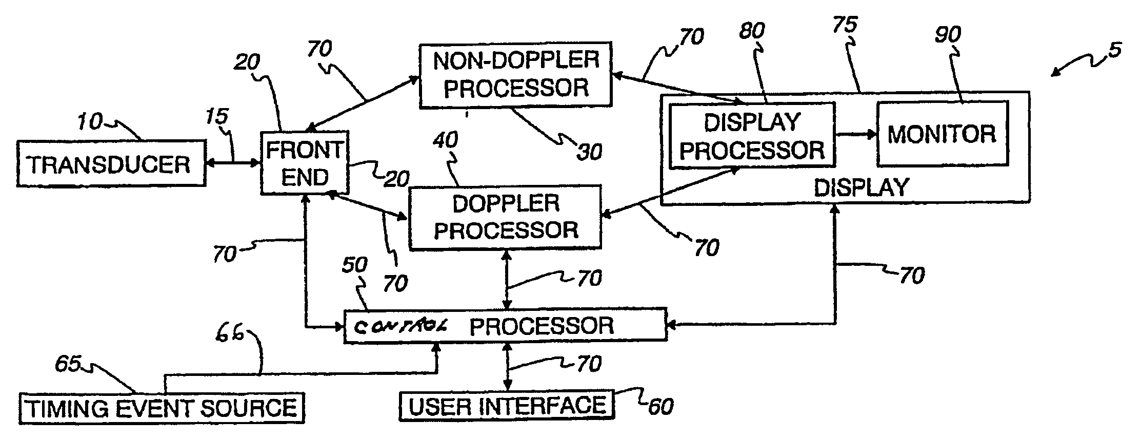
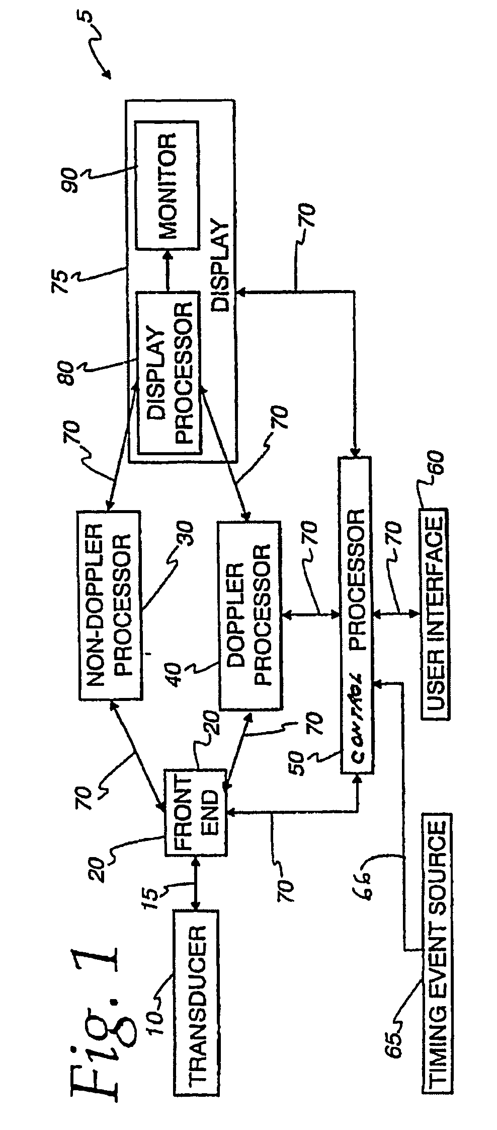
[0030]FIG. 1 illustrates an embodiment of an ultrasound machine, generally designated 5, in accordance with embodiments of the present invention. A transducer 10 transmits ultrasound waves into a subject by converting electrical analog signals to ultrasonic energy and receives the ultrasound waves backscattered from the subject by converting ultrasonic energy to analog electrical signals.

[0031] A front-end 20, that in one embodiment comprises a receiver, transmitter, and beamformer, may be used to create the necessary transmitted waveforms, beam patterns, receiver filtering techniques, and demodulation schemes that are used for the various imaging modes. Front-end 20 performs such functions, converting digital data to analog data and vice versa. Front-end 2...


PUM


Abstract

The present invention generally relates to ultrasound. In particular, the present invention relates to data dependent color wall filters (used in ultrasound imaging devices for example). Certain embodiments of the present invention relate to a color wall filter that provides flash reduction and clutter suppression. One embodiment of the color wall filter comprises an impulse response filter stage (either a finite or infinite impulse response filter) and a bi-quad filter stage that is data dependent. It is contemplated that the bi-quad filter stage may comprise a series of bi-quad filters, wherein the impulse response filter stage is cascaded into at least one bi-quad filter of the series of bi-quad filters.

Description

BACKGROUND OF THE INVENTION [0001] The present invention generally relates to ultrasound. In particular, the present invention relates to data dependent color wall filters used in imaging devices or systems for performing diagnostic ultrasound imaging. [0002] Known methods of performing diagnostic ultrasound imaging include B- and M-modes (used to image internal, physical structure), Doppler mode, and color flow mode. The color flow mode is primarily used to image flow characteristics, such as flow characteristics in blood vessels for example. Ultrasound color flow mode is typically used to detect the velocity of blood flow toward / away from an ultrasound transducer. Ultrasound color flow mode utilizes similar techniques used in Doppler mode. Whereas the Doppler mode displays velocity versus time for a single selected sample volume, ultrasound color flow mode displays hundreds of adjacent sample volumes simultaneously. The adjacent sample volumes are laid over a B-mode image and colo...

Claims


Application Information

Patent Timeline
IPC IPC(8): A61B8/00G01S15/89
CPCG01S15/8981
Inventor DUBBERSTEIN, DAVID
Owner GENERAL ELECTRIC CO
Learn More