
Inclined plate-type compressors and air conditioning systems including such compressors

a compressor and compressor body technology, applied in the field of inclined plate compressors, can solve the problems of significant and potentially damaging stress at the root portion of the valve body

Active Publication Date: 2005-11-10
SANDEN CORP
View PDF17 Cites 10 Cited by
  • Summary
  • Abstract
  • Description
  • Claims
  • Application Information

AI Technical Summary

Benefits of technology

[0006] Accordingly, a need has arisen for an inclined plate-type compressor wherein a discharge chamber having an annular shape is disposed along an outer circumferential portion of a cylinder head, a suction chamber is formed at a central portion of the cylinder head, and a discharge valve having reed valve-type valve bodies is disposed on the discharge chamber for opening and closing discharge ports formed in a valve plate, in which stress, generated at a root portion of each valve body when the valve body is opened or closed, may be reduced as compared with that in the above-described, known inclined plate-type compressors.
[0007] To satisfy the foregoing need and other objects, an inclined plate-type compressor according to the present invention, comprises a cylinder head, a discharge chamber having an annular shape and disposed along an outer circumferential portion of the cylinder head, a suction chamber formed at a central portion of the cylinder head, a valve plate comprising a plurality of discharge ports in communication with the discharge chamber, and a discharge valve comprising a plurality of reed valve-type valve bodies disposed in the discharge chamber. Each of the valve bodies opens and closes a corresponding one of the discharge ports, and each of the valve bodies extends in a circumferential direction of the discharge chamber and oriented along the annular shape of the discharge chamber. Because each valve body of the discharge valve extends in the circumferential direction of the annular discharge chamber, the length of each valve body may be increased as compared with that in the above-described known inclined plate-type compressors wherein the valve body extends in the radial direction of the annular discharge chamber. Therefore, in the present invention, a stress, generated at a root portion of each valve body when the valve body is opened or closed, may be reduced.
[0008] An air conditioning system, according to the present invention, comprises an inclined plate-type compressor. The compressor comprises a cylinder head, a discharge chamber having an annular shape and disposed along an outer circumferential portion of the cylinder head, a suction chamber formed at a central portion of the cylinder head, a valve plate comprising a plurality of discharge ports in communication with the discharge chamber, and a discharge valve comprising a plurality of reed valve-type valve bodies disposed in the discharge chamber. Each of the valve bodies opens and closes a corresponding one of the discharge ports, and each of the valve bodies extends in a circumferential direction of the discharge chamber and oriented along the annular shape of the discharge chamber. Because each valve body of the discharge valve extends in the circumferential direction of the annular discharge chamber, the length of each valve body may be increased as compared with that in the above-described known inclined plate-type compressors wherein the valve body extends in the radial direction of the annular discharge chamber. Therefore, in the present invention, a stress, generated at a root portion of each valve body when the valve body is opened or closed, may be reduced.

Problems solved by technology

In addition, a significant and potentially damaging stress may be generated at a root portion of the valve body when the valve body is opened or closed.

Method used


Image

  • Inclined plate-type compressors and air conditioning systems including such compressors
  • Inclined plate-type compressors and air conditioning systems including such compressors
  • Inclined plate-type compressors and air conditioning systems including such compressors

Examples


Embodiment Construction

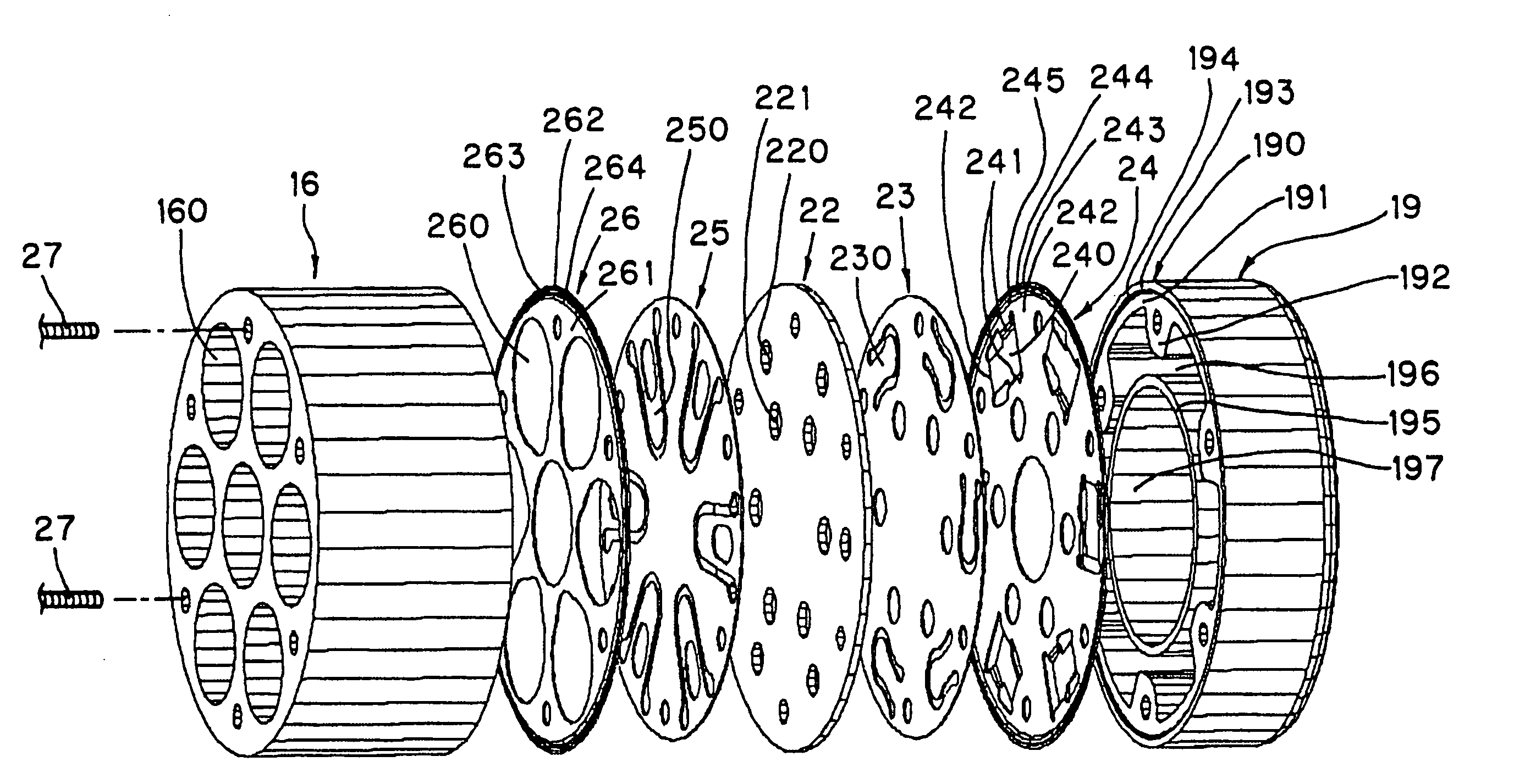
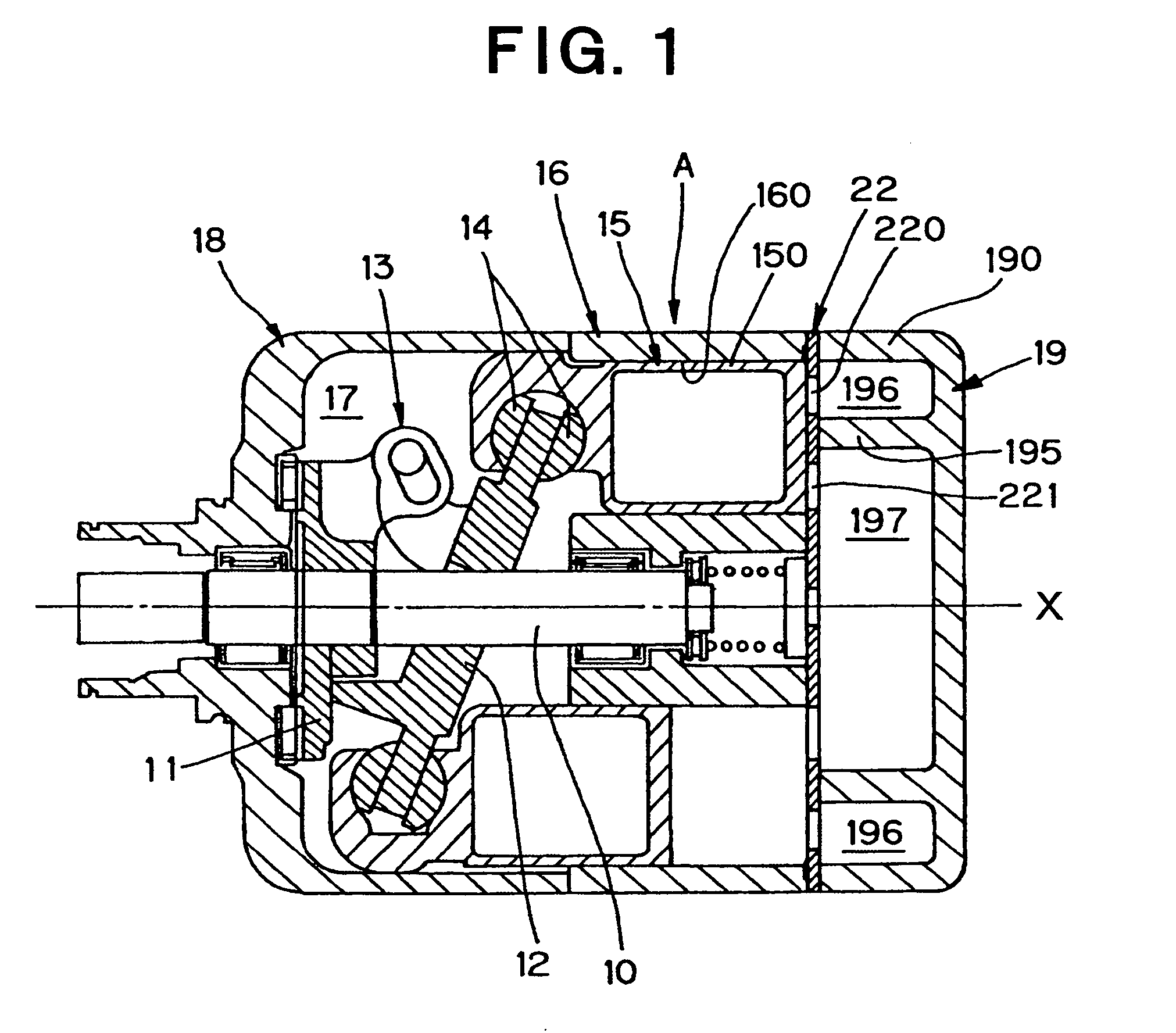
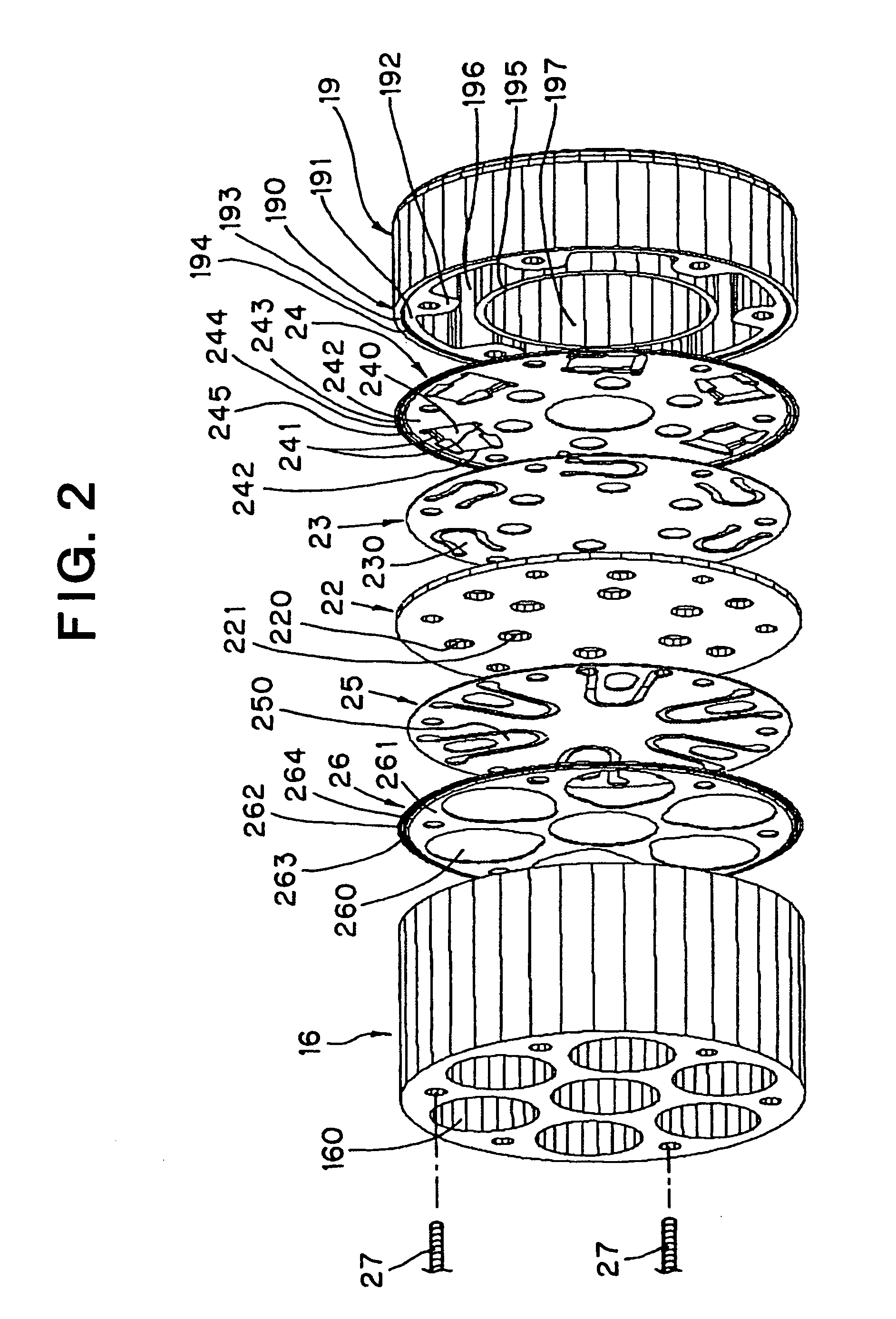
[0023]FIG. 1 depicts an inclined plate-type compressor according to an embodiment of the present invention. Inclined plate-type compressor A has a drive shaft 10, a rotor 11 which is secured to drive shaft 10, and an inclined plate 12 which is supported by drive shaft 10, such that the inclination angle of inclined plate 12 may be altered. In particular, inclined plate 12 is connected to rotor 11 via a link mechanism 13 adapted to allow the inclination angle of inclined plate 12 to be altered, and rotated synchronously with rotor 11 and, ultimately, with drive shaft 10.

[0024] Piston 15 engages inclined plate 12 via a pair of shoes 14 which slide on the outer circumferential portion of inclined plate 12. Piston head 150 of piston 15 is inserted into cylinder bore 160 formed in cylindrical cylinder block 16. A plurality of cylinder bores 160 are disposed around central axis X at a predetermined interval, and each piston head 150 of pistons 15 is inserted into one of cylinder bores 16...


PUM


Abstract

An inclined plate-type compressor includes a cylinder head, a discharge chamber having an annular shape and disposed along an outer circumferential portion of the cylinder head, a suction chamber disposed at a central portion of the cylinder head, a valve plate including discharge ports, and a discharge valve including reed valve-type valve bodies disposed in the discharge chamber. Each valve body opens and closes a corresponding discharge port, and each valve body extends in a circumferential direction of the discharge chamber and is oriented along the annular shape of the discharge chamber. Because each valve body extends in the circumferential direction of the discharge chamber, the length of each valve body may be increased as compared with that in known compressors, wherein the valve body extends in the radial direction over the width of the annular discharge chamber. Consequently, stress, which is generated at a root portion of each valve body when the valve body is opened or closed, may be reduced.

Description

BACKGROUND OF THE INVENTION [0001] 1. Field of the Invention [0002] The present invention relates to inclined plate-type compressors. Further, the invention relates to air conditioning systems, in particular, air conditioning systems for vehicles, which comprise such inclined plate-type compressors. [0003] 2, Description of Related Art [0004] An inclined plate-type compressor is described in Japanese Patent Application Publication No. JP-A-2002-250279, wherein a discharge chamber having an annular shape is disposed along an outer circumferential portion of a cylinder head, a suction chamber is formed at a central portion of the cylinder head, and a discharge valve having reed valve-type valve bodies disposed on the discharge chamber for opening and closing discharge ports is formed in a valve plate. In this inclined plate-type compressor, each of the valve bodies of the discharge valve extends in the radial direction of the discharge chamber, and the root portions of the valve bodie...

Claims


Application Information

Patent Timeline
IPC IPC(8): B60H1/00F04B1/12F04B27/08F04B27/10F04B39/00F04B39/10
CPCF04B27/1009F04B39/1073F04B27/1081
Inventor TAGAMI, SHINJI
Owner SANDEN CORP
Learn More