
System and Method for Restricting Access through a Mantrap Portal

a portal and system technology, applied in the field of security systems, can solve the problems of security breach, simple operation of a mantrap portal, and inability to restrict access through a mantrap portal

Inactive Publication Date: 2005-11-10
COGNEX TECH & INVESTMENT
View PDF42 Cites 81 Cited by
  • Summary
  • Abstract
  • Description
  • Claims
  • Application Information

AI Technical Summary

Benefits of technology

"The present invention provides better ways to control who can enter a secured area using a mantrap portal. The invention uses a sensor to continuously monitor two zones: a primary zone and a secondary zone. When the primary zone has no people and the secondary zone has no people, the invention can unlock the portal to allow access. The invention can detect and track people or objects using a three-dimensional machine vision sensor and a door access control system. The invention can also analyze the extreme extents of the zones and regions not captured by the sensors to detect any people or objects."

Problems solved by technology

A typical security issue associated with most access controlled portal security systems is to ensure that when a person is authorized for entry into a secured area, it is only that person that is permitted to enter.
The basic operation of a mantrap portal becomes increasingly complex as security of the portal is enhanced.
If a second, unauthorized person is permitted to enter the secured area with the authorized person, the security is breached.
Tailgating can occur when an authorized person knowingly or unknowingly provides unauthorized access through a portal to another traveling in the opposite direction.
For example, an unauthorized person entering the mantrap from the unsecured area can wait until someone leaves the secured area - and while the door is opened into the mantrap from the secured area, the unauthorized person can enter, thereby breaching security.

Method used


Image

  • System and Method for Restricting Access through a Mantrap Portal
  • System and Method for Restricting Access through a Mantrap Portal
  • System and Method for Restricting Access through a Mantrap Portal

Examples


Embodiment Construction

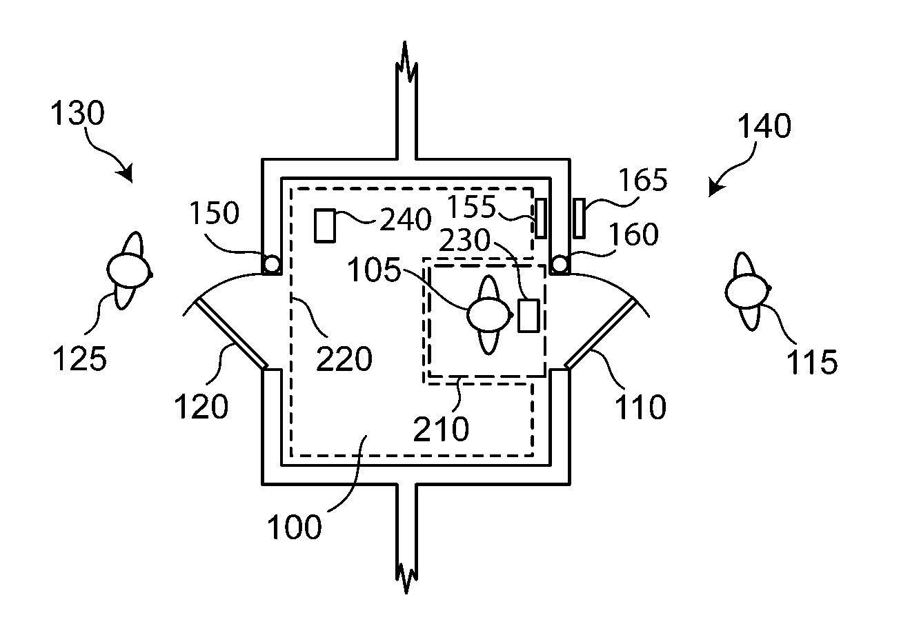
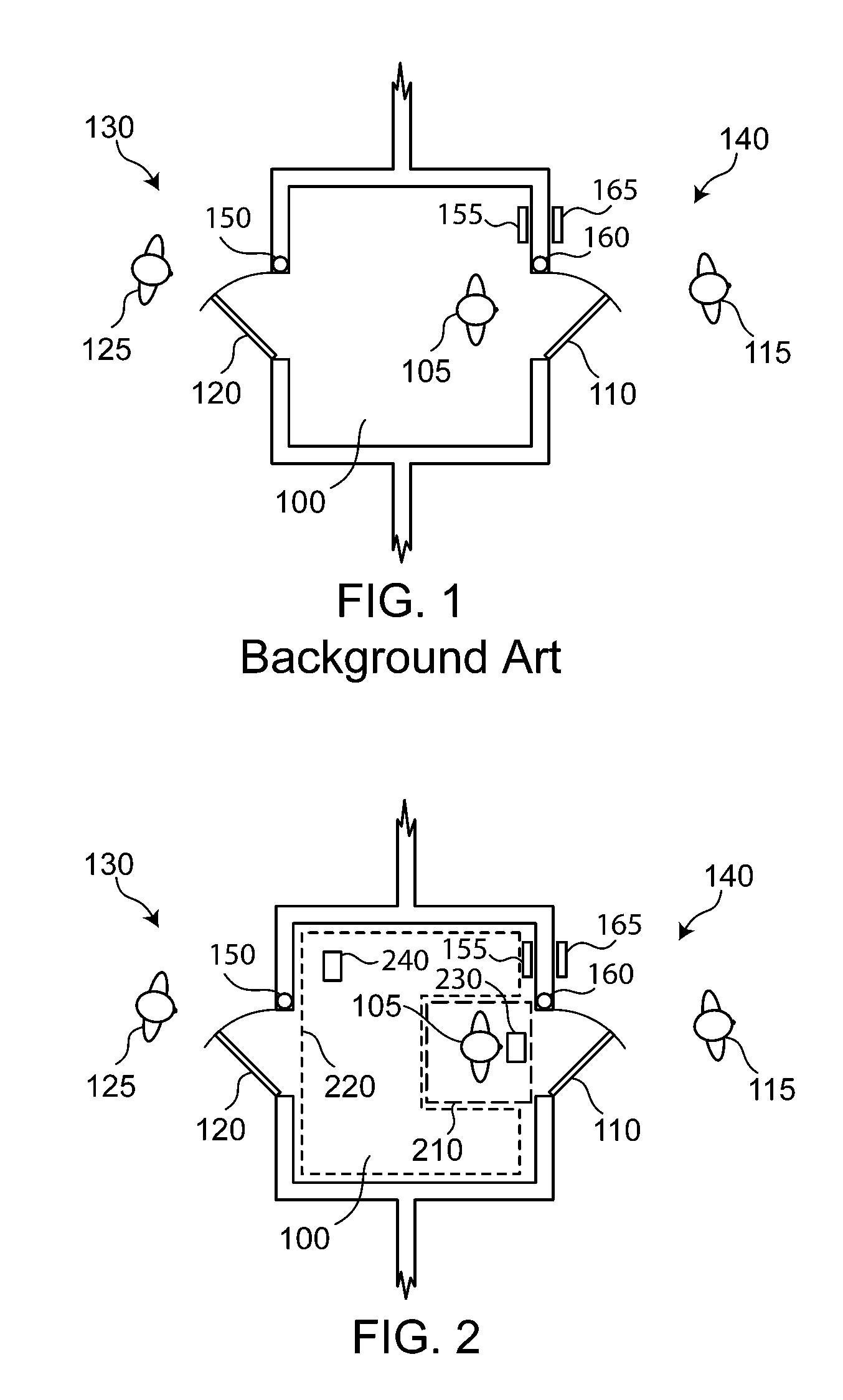
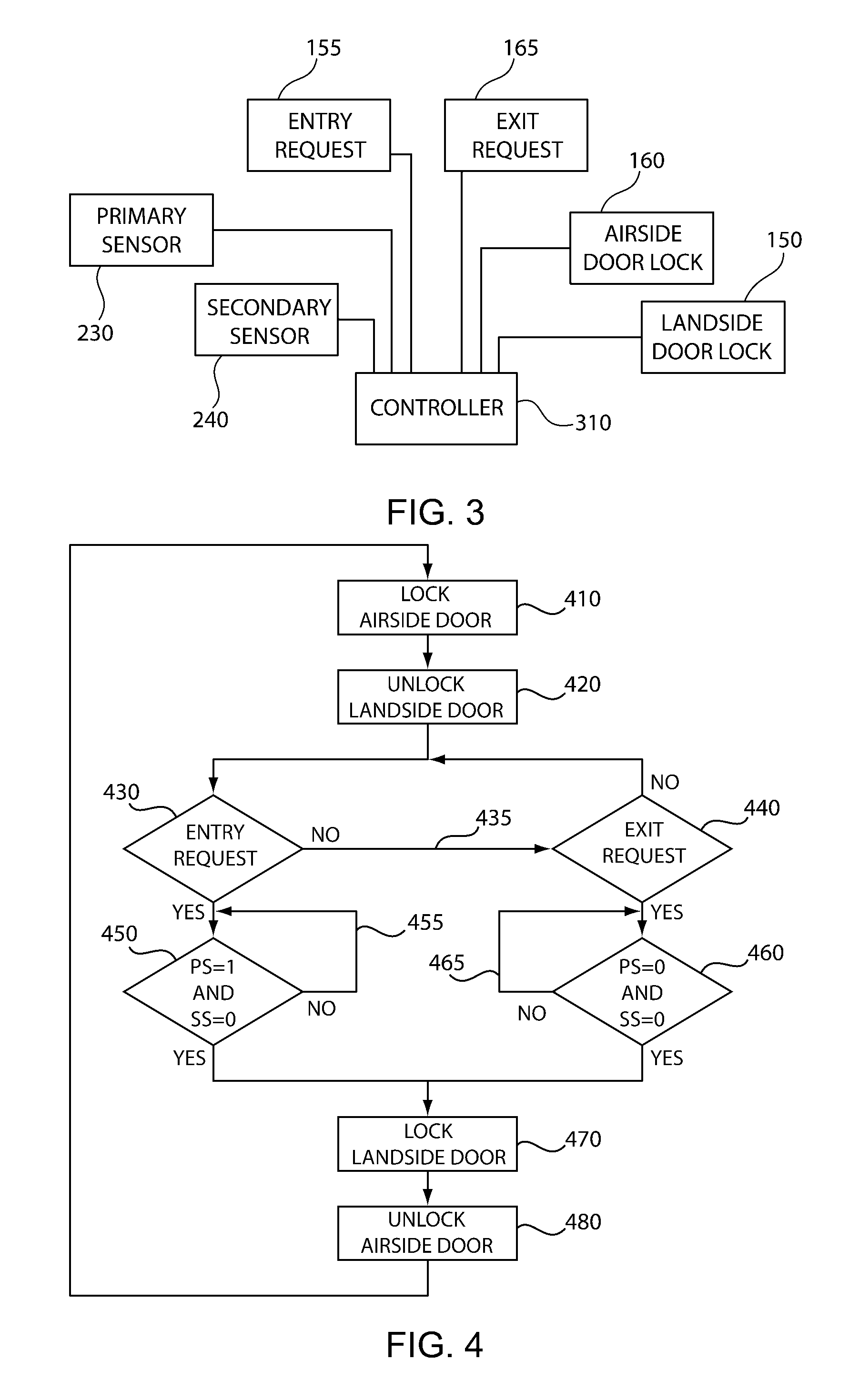
[0032] Referring to FIG. 2, in accordance with the present invention, there is provided a mantrap 100 to permit an enhanced level of security. The mantrap 100 is a portal region between an insecure landside region 130 and a secured airside region 140. The mantrap 100 has a landside door 120 for access into and out from the landside region 130, and an airside door 110, for access into and out from the airside region 140. An airside door lock 160 permits remote locking of the airside door 160, and a landside door lock 150 permits remote locking of the landside door 120. An access request 155 is shown as a panel for requesting access into the secure airside region 140, and an exit access 165 is shown as a panel for requesting access from the secured airside region 140 into the mantrap 100.

[0033] As shown in FIG. 2, a primary zone 210 is established as a region in the mantrap having an area less than the area of the mantrap 100. A primary sensor 230 monitors the primary zone 210 to det...


PUM


Abstract

A method and system provides increased levels of security for a mantrap portal by continuously monitoring two zones of the mantrap; a primary zone and a secondary zone. A primary sensor determines that exactly one or zero people are present in the primary zone when requesting access into a secured area. A secondary sensor determines that exactly zero people are present in the secondary zone when access to the secured area is granted. The primary and secondary sensors in combination can detect piggyback events and tailgating events before granting access to a secured area. Further, the primary and secondary sensors in combination can detect the presence of unauthorized persons in a mantrap prior to granting access to the mantrap for exit from a secured area.

Description

CROSS REFERENCE TO RELATED APPLICATIONS [0001] This application is a continuation-in-part to U.S. patent application Ser. No. 10 / 702,059, entitled “Method and System for Enhanced Portal Security through Stereoscopy,” filed Nov. 5, 2003, the contents of which are hereby incorporated by reference.BACKGROUND OF THE INVENTION [0002] This invention relates to security systems that permit controlled access to a secured area. Specifically, this invention relates to automatic door control in a secured area using a mantrap portal. [0003] A typical security issue associated with most access controlled portal security systems is to ensure that when a person is authorized for entry into a secured area, it is only that person that is permitted to enter. A mantrap secured portal is a configuration of a secured portal that is commonly employed for restricting access to that of only an authorized person at a time. [0004] A mantrap portal is a small room with two doors: one door for access to / from a...

Claims


Application Information

Patent Timeline
Patent Type & Authority Applications(United States)
IPC IPC(8): G06T7/00G06T7/20G06T15/10G07C9/00G07C9/02H04N13/00
CPCG06K9/00778G06T7/0075G07C9/025G07C9/00G06T7/20G06T7/593G07C9/15G06V20/53
Inventor SCHWAB, JOHNFIX, RAYMOND A.NICHANI, SANJAY
Owner COGNEX TECH & INVESTMENT
Learn More