
Power adapter with heat sink device

a technology of power adapters and heat sinks, which is applied in the direction of cooling/ventilation/heating modifications, solid-state devices, semiconductor devices, etc., can solve the problems of power adapters that cannot employ dispersing fans, the heat of the power transforming device is trapped in the insulating casing, and the power adapter cannot use a dispersing fan, so as to prevent heat from concentrating and even dispersing heat

Inactive Publication Date: 2005-11-10
ACBEL POLYTECH INC
View PDF8 Cites 25 Cited by
  • Summary
  • Abstract
  • Description
  • Claims
  • Application Information

AI Technical Summary

Benefits of technology

[0009] A main object of the present invention is to provide a power adapter with a heat sink device which is adapted to evenly disperse the heat from the power transforming unit in the insulating casing so as to prevent the heat from concentrating at a region of the insulating casing.
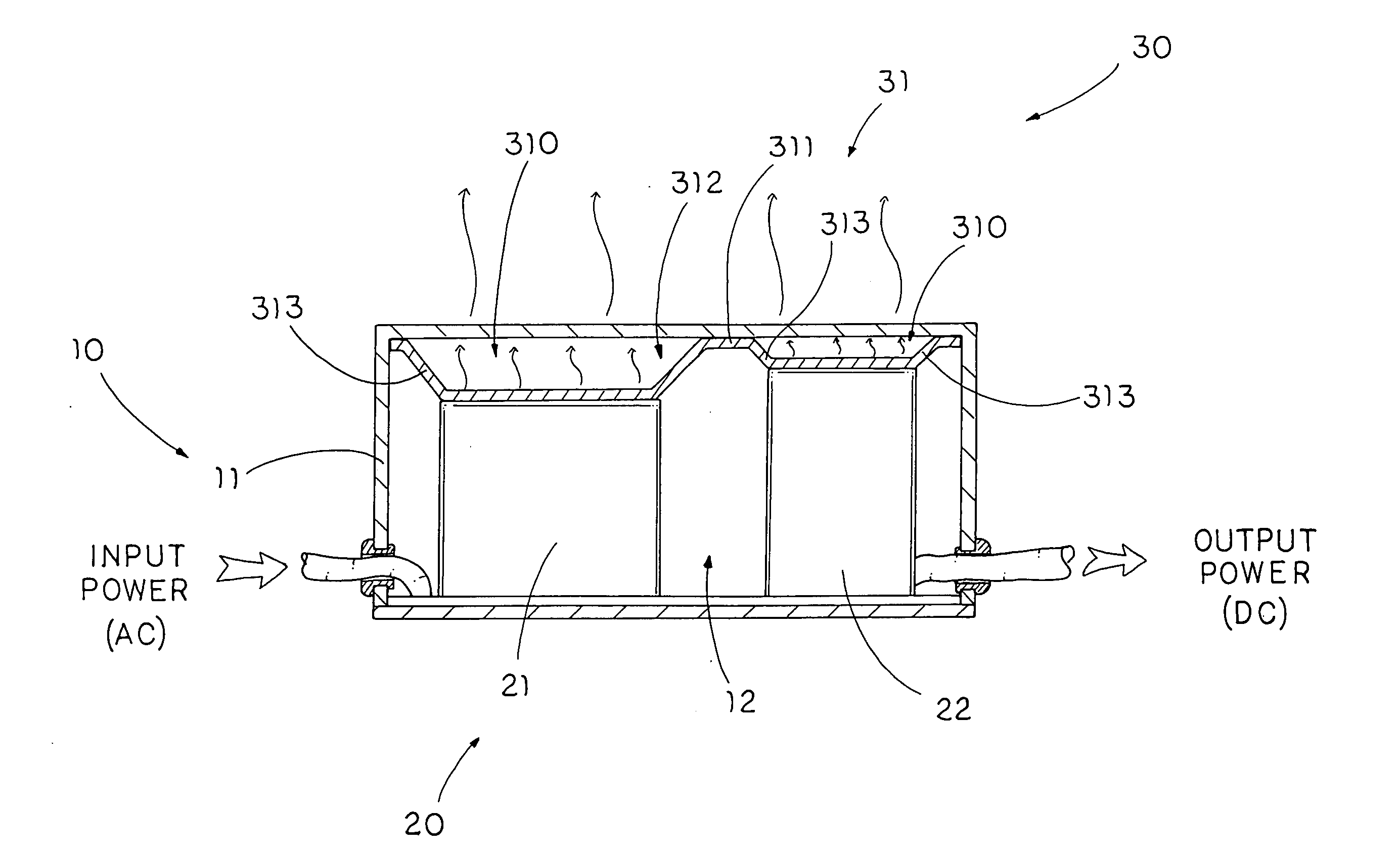
[0011] Another object of the present invention is to provide a power adapter with a heat sink device, wherein the air insulating cavity is positioned right above the power transforming unit such that when the air within the air insulating cavity is heated up by the power transforming unit, the air starts to circulate within the insulating casing so as to evenly spread out the heat on the enclosing wall of the insulating casing. In other words, the heat from the power transforming unit can be effectively dispersed to outside through the entire insulating casing.
[0012] Another object of the present invention is to provide a power adapter with a heat sink device, wherein the average surface temperature difference of the insulating casing is 2° C. when the operation of the power transforming unit in comparison with the conventional power adapter that the average surface temperature difference of the insulating casing is 5° C. during operation. In other words, it is safer for the user to touch the insulating casing during operation.
[0013] Another object of the present invention is to provide a power adapter with a heat sink device, wherein the power adapter does not require altering its original structure in order to incorporate with the heat sink device such that the heat sink device is adapted to install into any kind of power adapter having the insulating casing.
[0014] Another object of the present invention is to provide a power adapter with a heat sink device, wherein no expensive or complicated structure is required to employ in the present invention in order to achieve the above mentioned objects. Therefore, the present invention successfully provides an economic and efficient solution not only for providing a simple configuration for evenly dispersing the heat from the power transforming unit but also for enhancing the operation of the power adapter.

Problems solved by technology

However, the conventional power adapter has several drawbacks.
Since the power transforming device is sealed inside the insulating casing to prevent the user from being electric shock, the heat from the power transforming device is trapped in the insulating casing.
Unlike other device, the power adapter cannot employ a dispersing fan for dispersing the heat in the insulating casing to outside.
Therefore, the heat accumulated within the insulating casing will affect the normal operation of the power transforming device.
Accordingly, the average surface temperature difference of the insulating casing is 5° C. when the operation of the power transforming device such that it is dangerous when the user touches the insulating casing.
In addition, the heat applied on the particular region of the insulating casing will damage the insulating casing so as to loss the sealing insulation ability thereof.

Method used


Image

  • Power adapter with heat sink device
  • Power adapter with heat sink device
  • Power adapter with heat sink device

Examples


Embodiment Construction

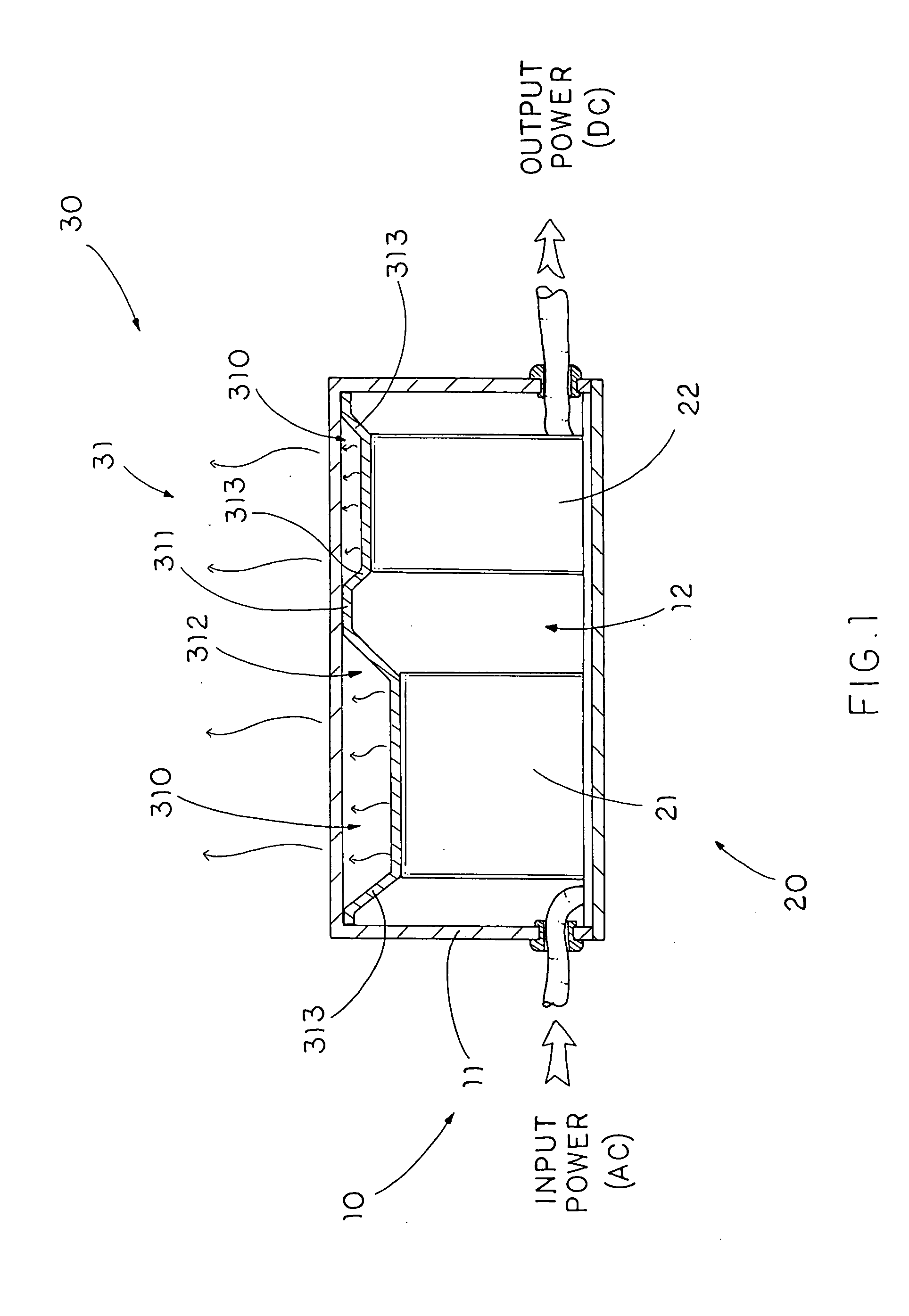
[0023] Referring to FIG. 1 of the drawings, a power adapter according to a preferred embodiment of the present invention is illustrated, wherein the power adapter comprises an insulating casing 10 which comprises an enclosing wall 11 and defines a sealing chamber 12 therein and a power transforming unit 20 disposed in the sealing chamber 12 for converting an input power into an output power.

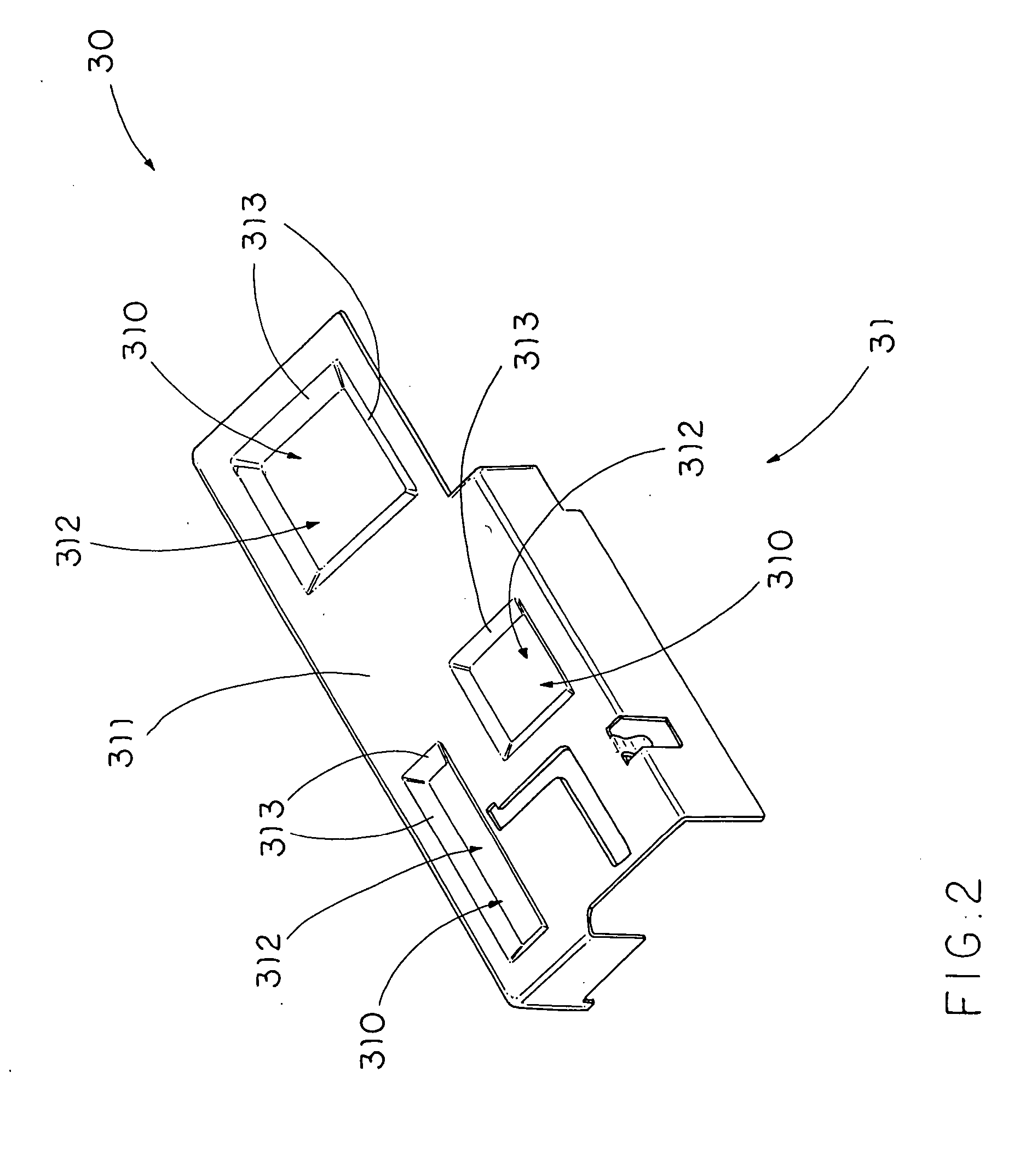
[0024] The power adapter further comprises a heat sink device 30 which comprises a heat dispersing member 31 supported within the sealing chamber 12 at a position between the enclosing wall 11 and the power transforming unit 20 to thermal-communicate with the power transforming unit 20, wherein the heat dispersing member 31 has an air insulating cavity 310 formed above the power transforming unit 20 in such a manner that when the power transforming unit 20 generates heat for heating up air within the air insulating cavity 310, the heat is diffused throughout the air insulating cavity 310 so as t...


PUM


Abstract

A power adapter includes an insulating casing including an enclosing wall and defining a sealing chamber therein, a power transforming unit disposed in the sealing chamber, and a heat sink device including a heat dispersing member supported within the sealing chamber at a position between the enclosing wall and the power transforming unit to thermal-communicate with the power transforming unit, wherein the heat dispersing member has an air insulating cavity formed above the power transforming unit in such a manner that when the power transforming unit generates heat for heating up air within the air insulating cavity, the heat is diffused throughout the air insulating cavity so as to evenly disperse on the enclosing wall of the insulating casing.

Description

BACKGROUND OF THE PRESENT INVENTION [0001] 1. Field of Invention [0002] The present invention relates to a power adapter, and more particularly to a power adapter with a heat sink device which is adapted to evenly disperse the heat from the power transforming unit in the insulating casing so as to prevent the heat from concentrating at a region of the insulating casing. [0003] 2. Description of Related Arts [0004] Power adapters are known as an electrical bridging device for providing an interface between a power source and an appliance. A conventional power adapter generally comprises an insulating casing and a power transforming device sealedly disposed in the insulating casing. The power transforming device generally comprises a transformer and a PFC (power factor correction) choke, such that when the power transforming device is electrically connected to the power source, the power transforming device is arranged to convert an AC Power from the power source to a DC power for the...

Claims


Application Information

Patent Timeline
Patent Type & Authority Applications(United States)
IPC IPC(8): H05K7/20
CPCH05K7/209H05K7/20445
Inventor HSU, CHENG-LUNG
Owner ACBEL POLYTECH INC
Learn More