
Container and lid assembly

a paint container and lid technology, applied in the field of paint containers and accessories, can solve the problems of difficult lid replacement, difficult removal of lids, hazardous practice, etc., and achieve the effect of convenient replacement of conventional paint cans

Active Publication Date: 2005-11-10
THE SHERWIN-WILLIAMS CO
View PDF35 Cites 13 Cited by
  • Summary
  • Abstract
  • Description
  • Claims
  • Application Information

AI Technical Summary

Benefits of technology

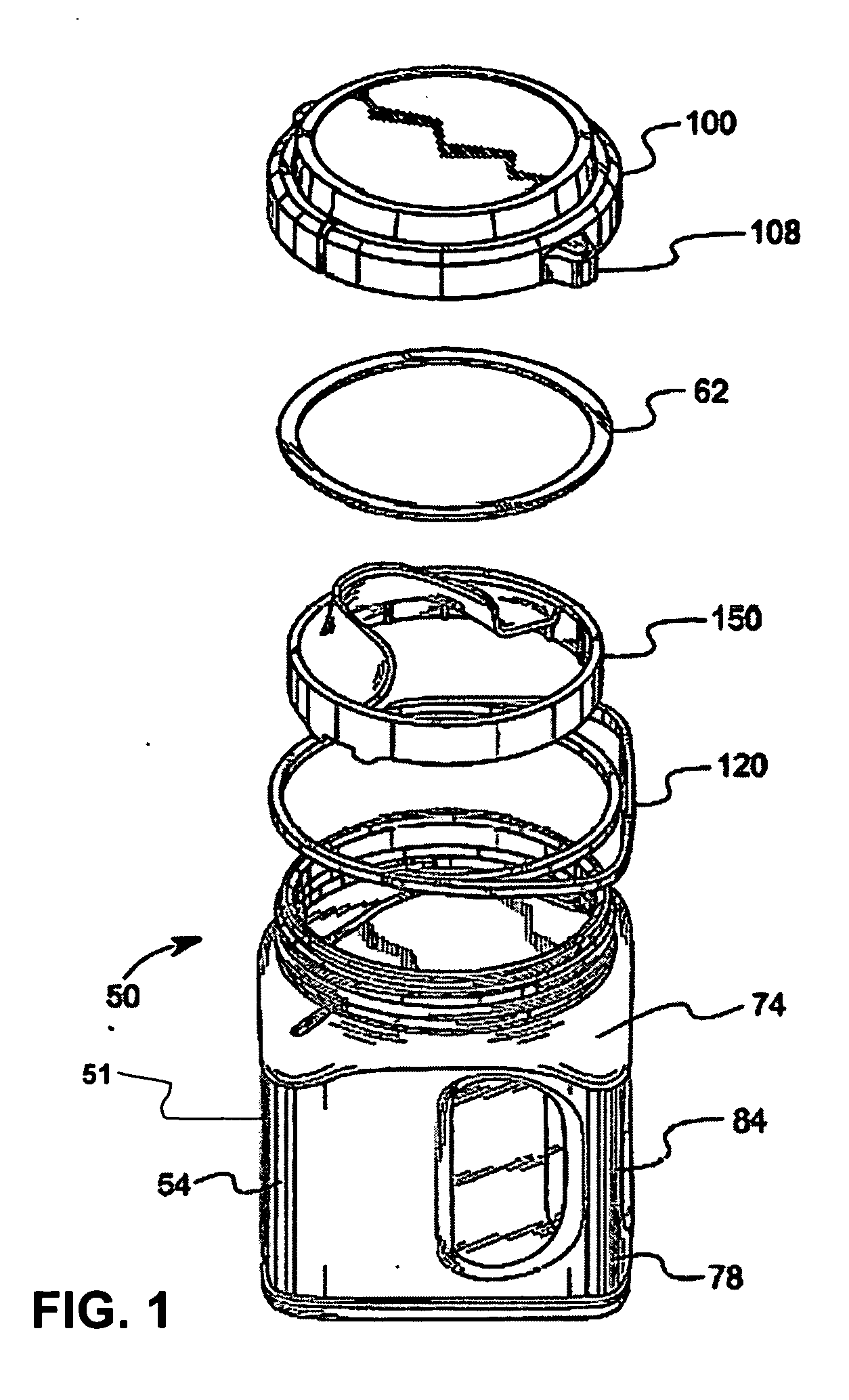
[0010] The present application provides an improved plastic container and lid assembly for storing liquid and coating materials. The assembly includes a container and a lid. The container has a body with a bottom wall, a sidewall and a neck. The sidewall may be a circular cross sectional configuration, or a rectangular configuration, in which case, at least four sidewalls are provided. Where four sidewalls are provided, the distance between one sidewall and an opposite sidewall is equal to the diameter of a conventional one gallon metal paint can or a conventional one quart metal paint can, depending on the size of the assembly. Moreover, the effective volume of the assembly is identical to that of a conventional paint can, such that the assembly of the present application may readily replace conventional paint cans.
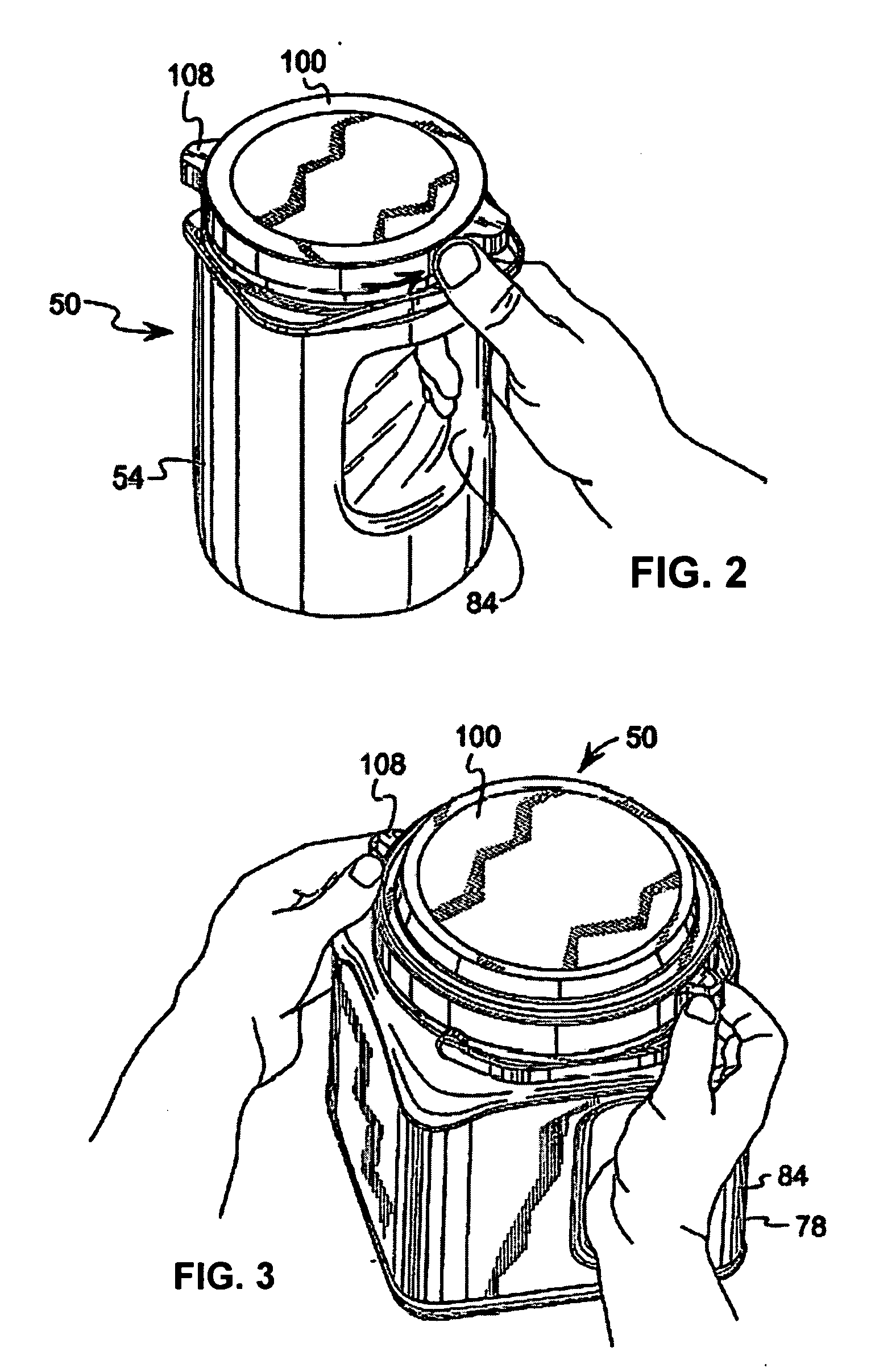
[0013] The integral handle included in the container body may be hollow, and is formed at one of the four corners of the container. When the lid is in sealed engagement on the container, one of the lugs is aligned over the integral handle. The integral handle forms a hollow vertical pillar within the body at the one corner of the body, with the pillar defining a cavity extending from one sidewall to an adjacent sidewall. The alignment of the lugs of the lid and bail-type handle over the corners of the container, within the boundaries of the sidewalls of the container during sealing engagement of the lid on the container, also facilitates the replacement of conventional metal paint cans by the present assembly. When all elements of the assembly are aligned within the boundary of the sidewalls, the effective packing footprint of the assembly is substantially equal to that of a conventional paint can.

Problems solved by technology

First, removal of the lid requires a prying tool and can be difficult.
Replacement of the lid may also be difficult because a hammer or mallet is often required to completely reseat opposed mating grooves on the lid and container and to effectively seal the container.
This practice may be hazardous if one loses their balance, and messy when paint remains in the container grooves as a result of the pouring process.
Over time, due to the moisture inherent within the paint, metal pails and lids have a tendency to rust or corrode.
If rust pieces fall into the paint, they often render the paint useless.
Metal paint cans are also susceptible to impact damage when they are dropped, or impacted from the side.
Once the can is deformed, seating and reseating the lid can be difficult and it is difficult and often impossible to return the can to a desired shape.
Pouring paint from metal paint cans is yet another difficult task due to the can's configuration.
Flowing paint is difficult to guide because no spout formation exists upon the can.
The result is a messy container, which is difficult to open upon next use.
Manufacture of paint cans has also been difficult.
The formation and attachment of metal wire bail handles is a difficult task to perform.
However, pouring paint from conventional containers for use in these types of applicators can be messy.
However, in other cases, a larger supply of paint is needed for powered sprayers or rollers.

Method used


Image

  • Container and lid assembly
  • Container and lid assembly
  • Container and lid assembly

Examples


Embodiment Construction

[0064] It will be appreciated that the illustrated boundaries of elements (e.g., boxes or groups of boxes) in the figures represent one example of the boundaries. One of ordinary skill in the art will appreciate that one element may be designed as multiple elements or that multiple elements may be designed as one element. An element shown as an internal component of another element may be implemented as an external component and vice versa.

[0065] Further, in the accompanying drawings and description that follow, like parts are indicated throughout the drawings and description with the same reference numerals, respectively. The figures are not drawn to scale and the proportions of certain parts have been exaggerated for convenience of illustration.

[0066] Referring to FIG. 1, a schematic view of the components of the container 50 and lid 100 assembly is shown. The assembly comprises a container 50 having an integral handle 84, a bail handle 120, a pouring insert 150, and a lid 100 h...


PUM


Abstract

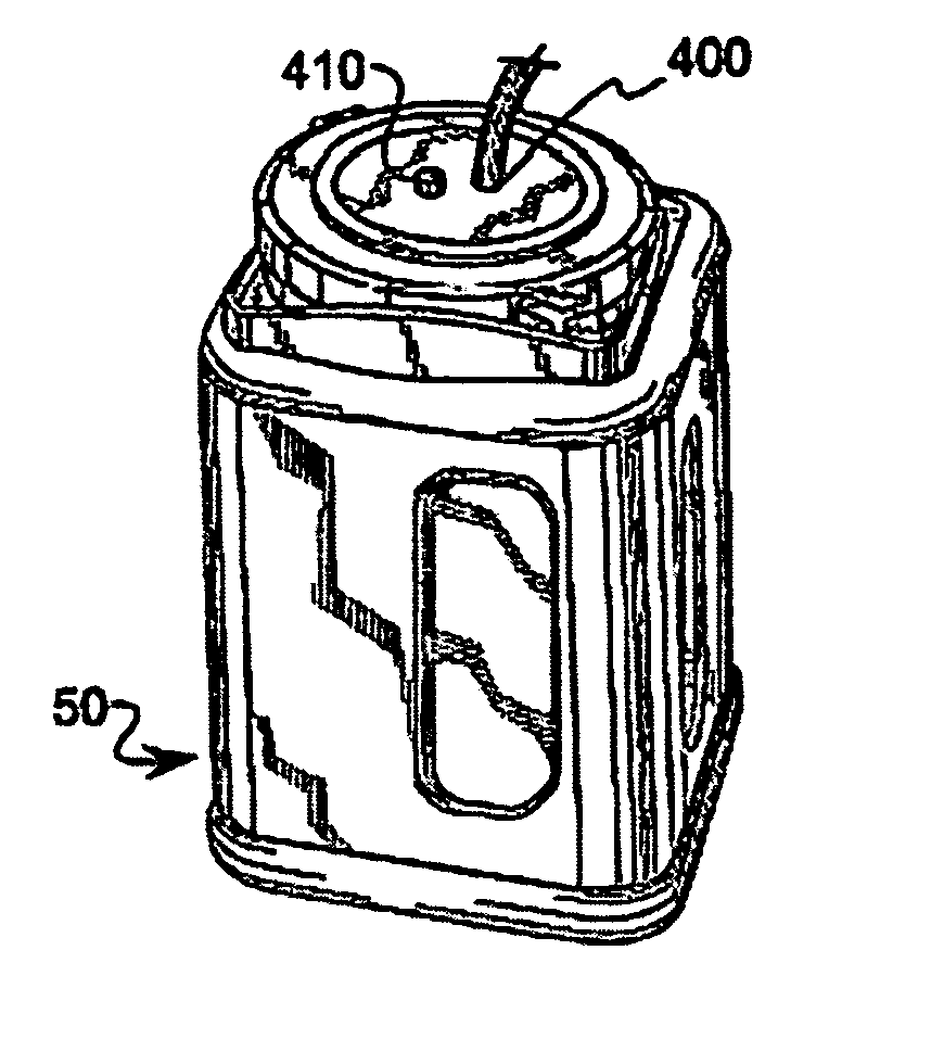
An assembly for facilitating the use of paint applicator accessories in connection with a plastic container is provided. The assembly includes a nozzle device housed within a container lid and having a suction line, which extends into the paint container. The assembly also includes one or more vent holes. The assembly can be used to supply paint to a paint applicator device by attaching an intake conduit of the paint applicator to the nozzle device. As paint is siphoned out of the container by the applicator device, the vent holes allow air to flow into the container to replace the volume of withdrawn paint.

Description

RELATED APPLICATION DATA [0001] This application claims priority from U.S. Provisional Application No. 60 / 557,860 filed Mar. 31, 2004, and U.S. Provisional Application No. 60 / 603,226 filed on Aug. 20, 2004. The disclosures of both Provisional Applications 60 / 557,860 and 60 / 603,226 are hereby incorporated by reference. In addition, this application is related to U.S. patent application Ser. No. 10 / 126,481 filed Apr. 18, 2002, which claims priority from U.S. Provisional Application No. 60 / 284,476 filed Apr. 18, 2001 and U.S. Provisional Application No. 60 / 292,364 filed on May 21, 2001, all of which are hereby incorporated by reference.TECHNICAL FIELD [0002] This application relates generally to paint containers and accessories for use therewith, and more specifically to a lid assembly for a paint container which accommodates paint container accessories which remove paint from the container for application. BACKGROUND [0003] The most common way to store paints or other coatings has bee...

Claims


Application Information

Patent Timeline
IPC IPC(8): B05CB44D3/12B65D17/52
CPCB44D3/127B44D3/12
Inventor NOTTINGHAM, JOHN R.SPIRK, JOHN W.PANASEWICZ, DALE A.IREDELL, ROBERTSTANCA, NICK E.
Owner THE SHERWIN-WILLIAMS CO
Learn More