
Jet nozzle mixer

a technology of mixers and nozzles, which is applied in the direction of machines/engines, jet propulsion plants, etc., can solve the problems of difficult and expensive manufacturing of lobes, impractical engine reconfiguration, and high cost of mixers to be retrofitted to engines, and achieve the effect of reducing nois

Inactive Publication Date: 2005-11-10
ANDERSON JACK
View PDF28 Cites 2 Cited by
  • Summary
  • Abstract
  • Description
  • Claims
  • Application Information

AI Technical Summary

Benefits of technology

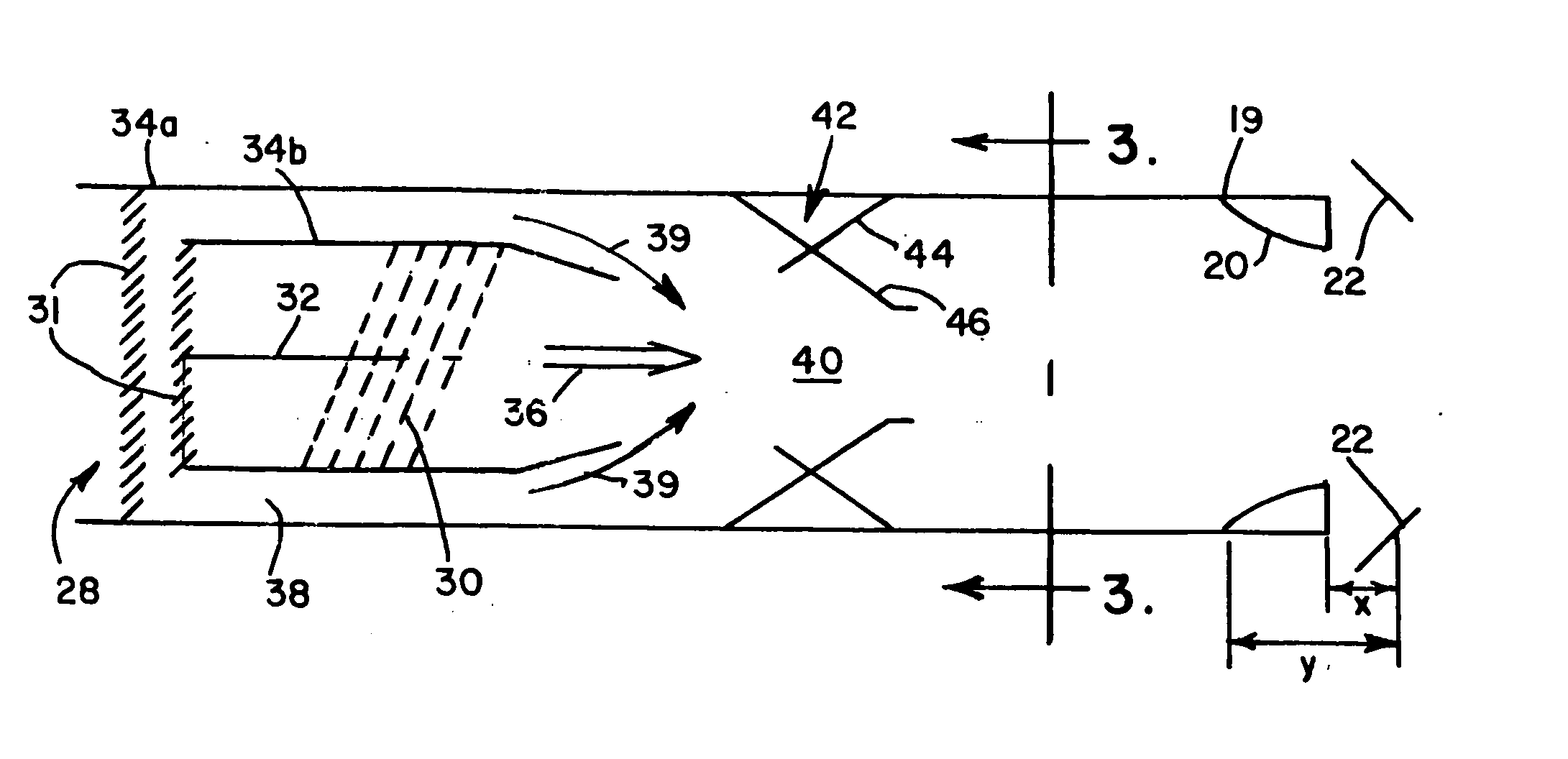
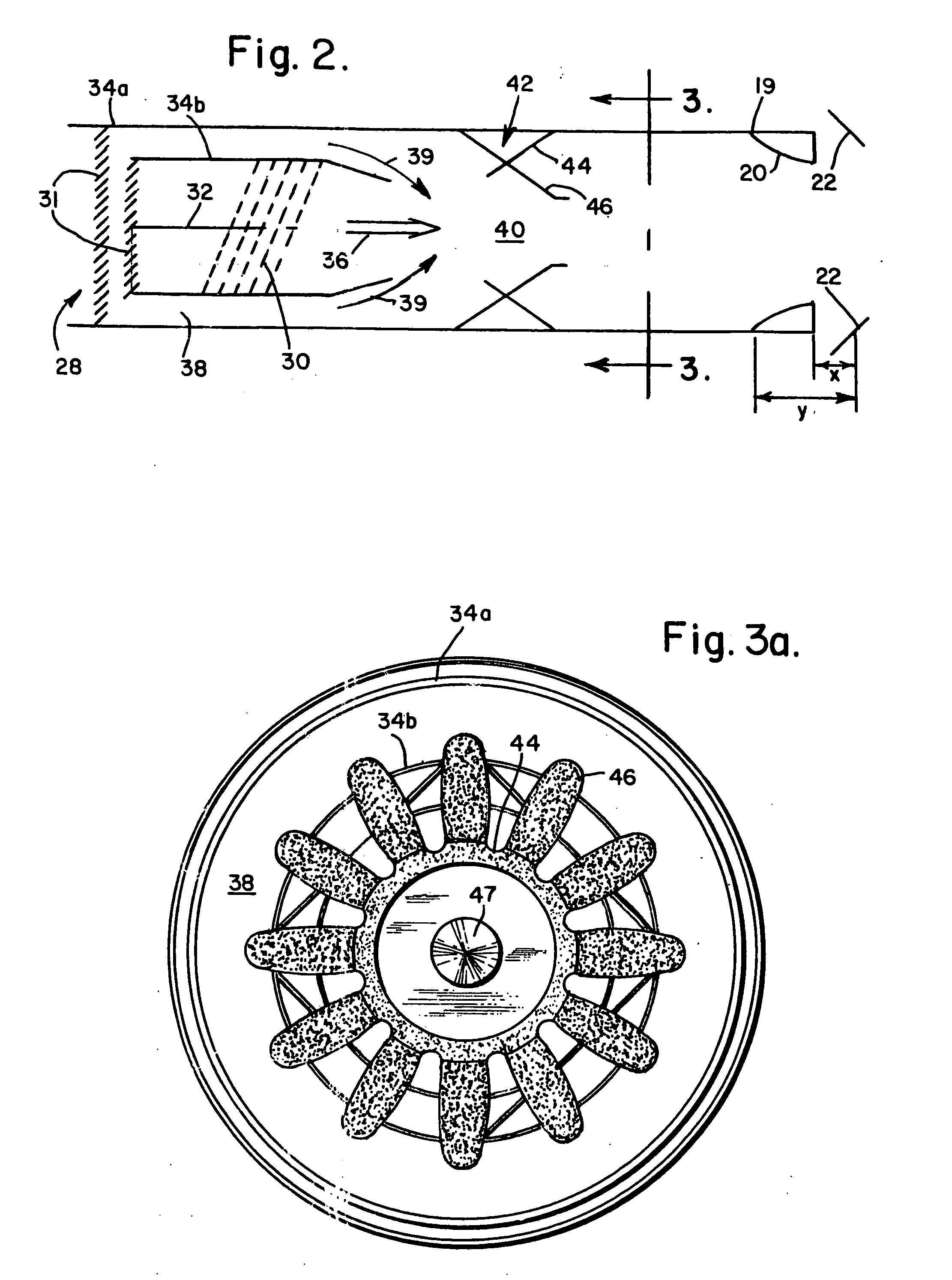
[0005] These and other problems are avoided and the Stage 4 / Chapter 4 requirements are both met and surpassed by the present invention, not only for the above-mentioned Pratt & Whitney JT8D-217 / 219 Series engine but also for other engines. The second stage or external jet nozzle mixer of the present invention includes a number of lobes, which may be equal in number to those of the first stage or internal mixer, and all of the second stage mixer lobes may be identically formed. As the lobes axially extend outwardly from the mixer attachment to the engine nozzle, they axially inwardly expand from an essentially circular base to an undulating configuration whose apices increase in height. The lobes include complex curvatures whose interior and exterior surfaces greatly enhance mixing respectively of the previously mixed bypass cooling air-hot exhaust gases from the internal mixer and additional ambient cooling air, and thereby also reduce noise. At their terminus, the area encompassed by the lobes remains essentially the same (1,065 to 1,120 sq. inches) as for the jet engine for which it is designed which, for the Pratt & Whitney JT8D-217 / 219 Series engine, is 1,095 to 1,105 square inches (6,089 to 7,097 square centimeters). For other engines, the lobe terminus area is consistent with that of the engine in question.
[0007] The exit shape has elliptical shaped lobes and is proportional to a 10×2.5 ellipse (plus or minus 2 inch major axis, and +0.5 inch minor axis). These curve sides help resist distortion caused by the exhaust gas pressure.
[0009] Functionally, the interior surfaces of the lobes force the impinging hot gases, as previously mixed with the secondary bypass cooling air by the first set of lobes of the internal mixer, in all directions towards the interior of the mixer, essentially 45° to 60°, to effect a vigorous mixing of the gases. Simultaneously, additional ambient cooling air is forced from the exterior surfaces of the lobes to mix further with the internally mixed gases. These actions cause the smaller gas cores, which were formed by the first stage mixer, to break into innumerable forms which are both cooler and considerably noise attenuated. In part, the internal contours of the lobes act as flutes to produce a lifting effect which causes the primary hot and cold flows to mix before entering the nozzle. The external contours of the lobes act as chutes which produce a venturi effect and accelerate the cooler secondary flow of ambient air. The lobes thereby act collectively as an injector to force the cooler ambient secondary flow into the previously mixed primary flow as it exits the nozzle. These actions further reduce the noise level. Further, the curve sides of the lobes help resist distortion caused by the exhaust gas pressure. An ameliorative further result is that the accelerated gas / air flow helps to faster move large, previously slowed mixtures to increase the efficiency of the jet engine, by increasing its thrust, that is, an increased thrust specific fuel consumption (TSFC) is estimated to be about a 3% improvement. Such increased TSFC occurs through better dynamic mixing of the bypass or fan duct and turbine exhaust gases. It addresses the problem of the transfer from a hot, high velocity volume to a cooler, slower velocity volume. This mixing levels the disparate flow velocities attendant with the jet engine exhaust, reduces the peak velocities from the jet engine core and increases the lower bypass velocities of the jet engine internal bypass flow. Because noise is a function of jet exhaust velocity to the 7th power, and because peak velocities from the core flow are reduced, the jet noise is thereby reduced.
[0010] As stated above, the axial length of the mixer of the present invention is 12 inches±3 inches, which means that there is a lesser distance between the nozzle exit and the buckets of the thrust reverser. The effect of such decreased distance is that more of the thrust from the engine is captured by the buckets and thus utilized to brake the aircraft when needed.
[0011] Several advantages are derived from this arrangement. The jet nozzle mixer of the present invention fits within and is attachable to the existing engine exit whose area which, as stated above, is 1,095-1,105 square inches (6,261-7,129 square centimeters) exit area for the Pratt & Whitney JT8D-217 / 219 Series engine. The lobes of the present invention can be made uniform and easily tailored to provide an efficient mixing of the exhaust gases with the ambient air and the attendant reduction in noise. Its uniform dimensions enables its manufacturing costs to be reduced. The need to modify the existing thrust reverser per se is avoided because the mixer is fittable and attachable to the existing engine exit; only minor dimensional changes in the existing STANG fairing, and tailpipe and outer barrel are required without otherwise needing any change in other components such as the thrust reverser, the thrust reverser doors, and their linkages. Efficiency in jet engine operation is increased, with concomitant saving of fuel and costs thereof. Thrust reverser braking of the aircraft is improved.

Problems solved by technology

Such engine reconfiguration is impractical and expensive.
Therefore, the direction towards meeting Stage 3 / Chapter 3 noise requirements has been involved in developing a variously configured second set of lobes whose design does not always meet such requirements and, when the lobe design does, the lobes are difficult and expensive to manufacture and the mixer is expensive to be retrofitted to the engine.
Such an upgrading is a challenge that has not been met.

Method used


Image

  • Jet nozzle mixer
  • Jet nozzle mixer
  • Jet nozzle mixer

Examples


Embodiment Construction

[0029] Because the present invention was devised particularly with respect to the Pratt & Whitney JT8D-217 / 219 Series engine, the following discussion will be directed specifically thereto; however, it is to be understood that the present invention is equally relevant for use in other jet engines and, therefore, is not to be limited to a specific jet engine.

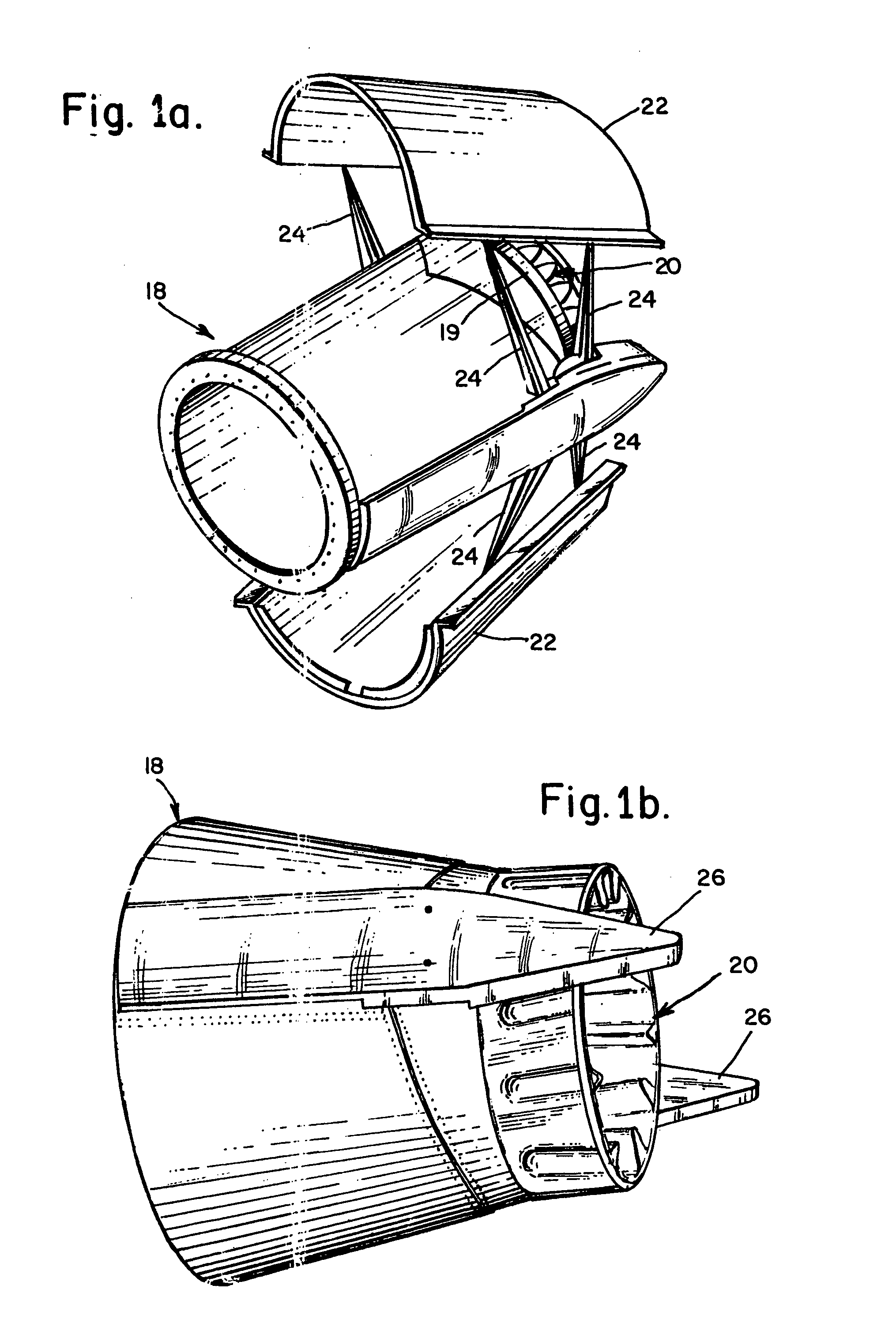
[0030] Accordingly, FIGS. 1a and 1b illustrate a nozzle assembly 18 relating to, for example, a Pratt & Whitney JT8D-217 / 219 Series jet engine to which a jet nozzle mixer 20 as embraced by the present invention is attached at its exhaust terminus 19. Assembly 18 also supports a thrust reverser having a pair of thrust reverser buckets 22. The attachment of the thrust reverser buckets to assembly 20 is effected by bars 24 which are pivotally linked to a pair of diametrically opposed mechanisms housed within fairings 26, one of which is shown in FIG. 1. The fairings are secured at opposite sides of the assembly. The thrust reverser...


PUM

PropertyMeasurementUnit
areaaaaaaaaaaa
lengthaaaaaaaaaa
lengthaaaaaaaaaa

Abstract

An external jet nozzle mixer includes identically formed lobes. The external mixer works with the internal mixer further to mix the engine internal bypass flow with the internal jet engine core flow to level the disparate flow velocities, to reduce the peak velocities from the jet engine core and increase the lower bypass velocities of the engine internal bypass flow, and thereby reduce noise. The internal lobe contours act as lifting flutes, causing mixing of the primary hot and cold flows to mix before exiting the nozzle. The external lobe contours act as venturi chutes, accelerating the cooler ambient secondary air flow. The lobes thus act collectively as an injector to force the cooler ambient secondary flow into the previously mixed primary flow as it exits the nozzle. Also obtained is an increased thrust efficiency and a consequently decreased fuel consumption and engine emissions.

Description

CROSS-REFERENCE TO RELATED APPLICATIONS [0001] This application is a continuation of application Ser. No. 10 / 314,101, filed Dec. 7, 2002, which claims the benefit of U.S. Provisional Application No. 60 / 340,369, filed Dec. 7, 2001, each of which is incorporated herein by reference thereto, respectively.FIELD OF THE INVENTION [0002] The present invention relates to jet nozzle mixers for aircraft jet engines and, in particular, to improvements in effecting a greater cooling and a lower noise level in exhaust gases emanating from such engines and in increasing power and fuel efficiency. BACKGROUND [0003] Noise (decibel) level in jet aircraft engines is established by laws and regulations, specifically promulgated by the International Civil Aviation Organization (ICAO), Annex 16. At present, commercial jet aircraft weighing over 75,000 pounds (34,000 kilograms) must meet Stage 3 / Chapter 3 noise (decibel) level requirements which establish an allowable decibel noise level. Under Annex 16 ...

Claims


Application Information

Patent Timeline
Patent Type & Authority Applications(United States)
IPC IPC(8): F02K1/46F02K1/48F02K1/70F02K3/02
CPCF02K1/46F02K1/48Y10T29/49346F02K3/02F02K1/70
Inventor ANDERSON, JACK
Owner ANDERSON JACK
Learn More