
Apparatus for and method of analyzing transmission characteristics of a circuit apparatus

a circuit apparatus and transmission characteristic technology, applied in the field of circuit apparatus and transmission characteristics analysis apparatus, can solve the problems of circuit apparatus not transmitting data normally, circuit apparatus may fail to generate mesh and analyze electromagnetic field for a long time, and current loss also increases

Inactive Publication Date: 2005-11-03
FUJITSU LTD
View PDF0 Cites 10 Cited by
  • Summary
  • Abstract
  • Description
  • Claims
  • Application Information

AI Technical Summary

Benefits of technology

[0010] Accordingly, it is a general object of the present invention to provide a novel and useful method and apparatus in which one or more of the problems described above are eliminated.
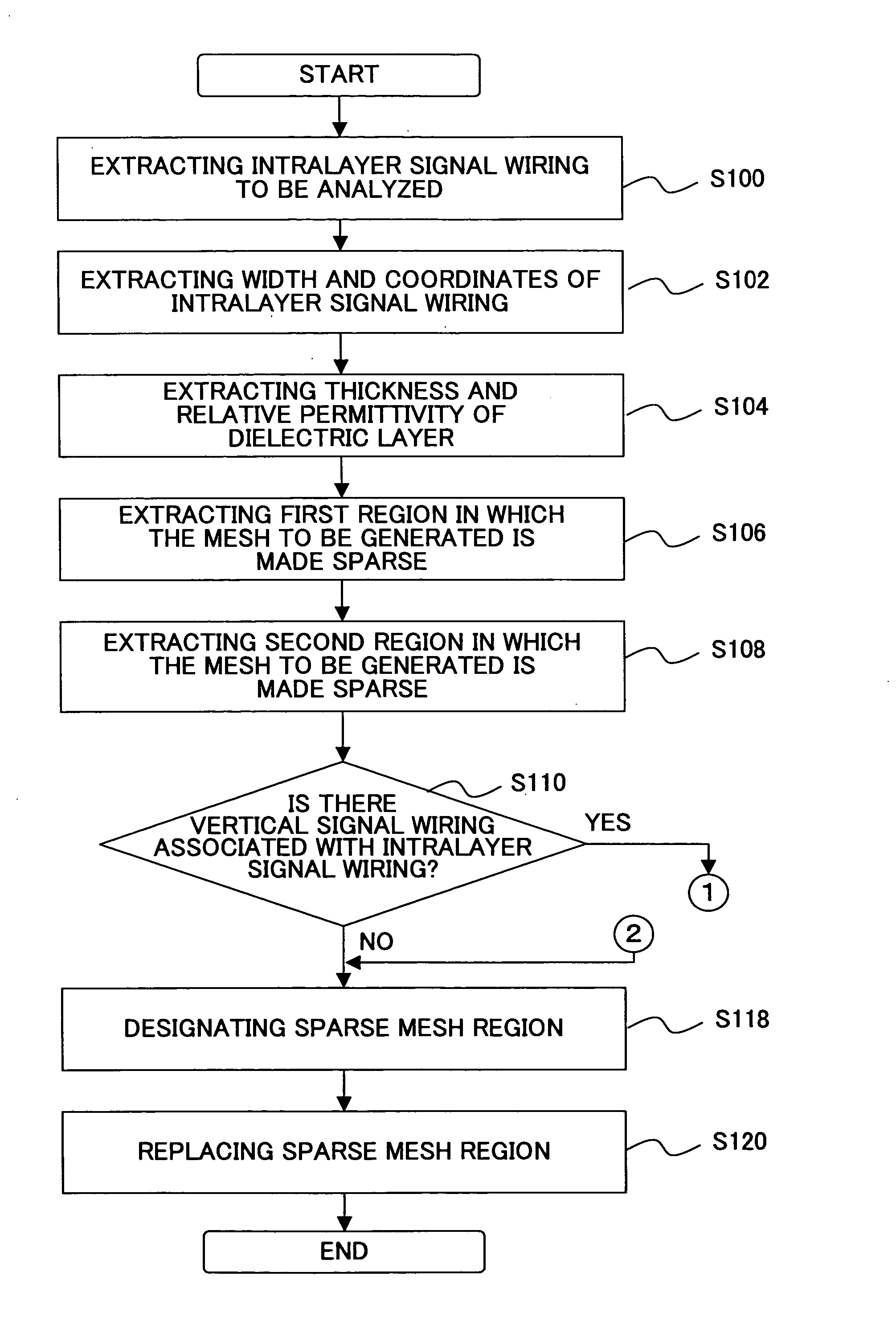
[0013] Since the sparse mesh region is-designated based on the sizes of the signal wiring and the insulative layer and on the electric properties of the insulative layer, a region that affects the transmission characteristics of the signal wiring only to a small extent can be designated as the sparse mesh region. Accordingly, the number of the units of mesh (mesh units) can be reduced (the mesh is made sparse) and consequently, the time required for the analysis of the circuit apparatus can be reduced by changing at least one property of the designated sparse mesh region.

Problems solved by technology

In addition, since a reflection factor increases, current loss also increases.
In such a case, if the signal integrity of the circuit apparatus is not verified, the circuit apparatus may fail to transmit data normally.
The problem is that a long time is required for generating the mesh and analyzing the electromagnetic field in such regions.
However, the problem is that the 3 dimensional data needs to be modified for dividing the circuit apparatus into multiple portions, and the electric property parameters obtained as a result of the electromagnetic analysis need to be combined.

Method used


Image

  • Apparatus for and method of analyzing transmission characteristics of a circuit apparatus
  • Apparatus for and method of analyzing transmission characteristics of a circuit apparatus
  • Apparatus for and method of analyzing transmission characteristics of a circuit apparatus

Examples


Embodiment Construction

[0024] The preferred embodiment of the present invention are described below with reference to the drawings.

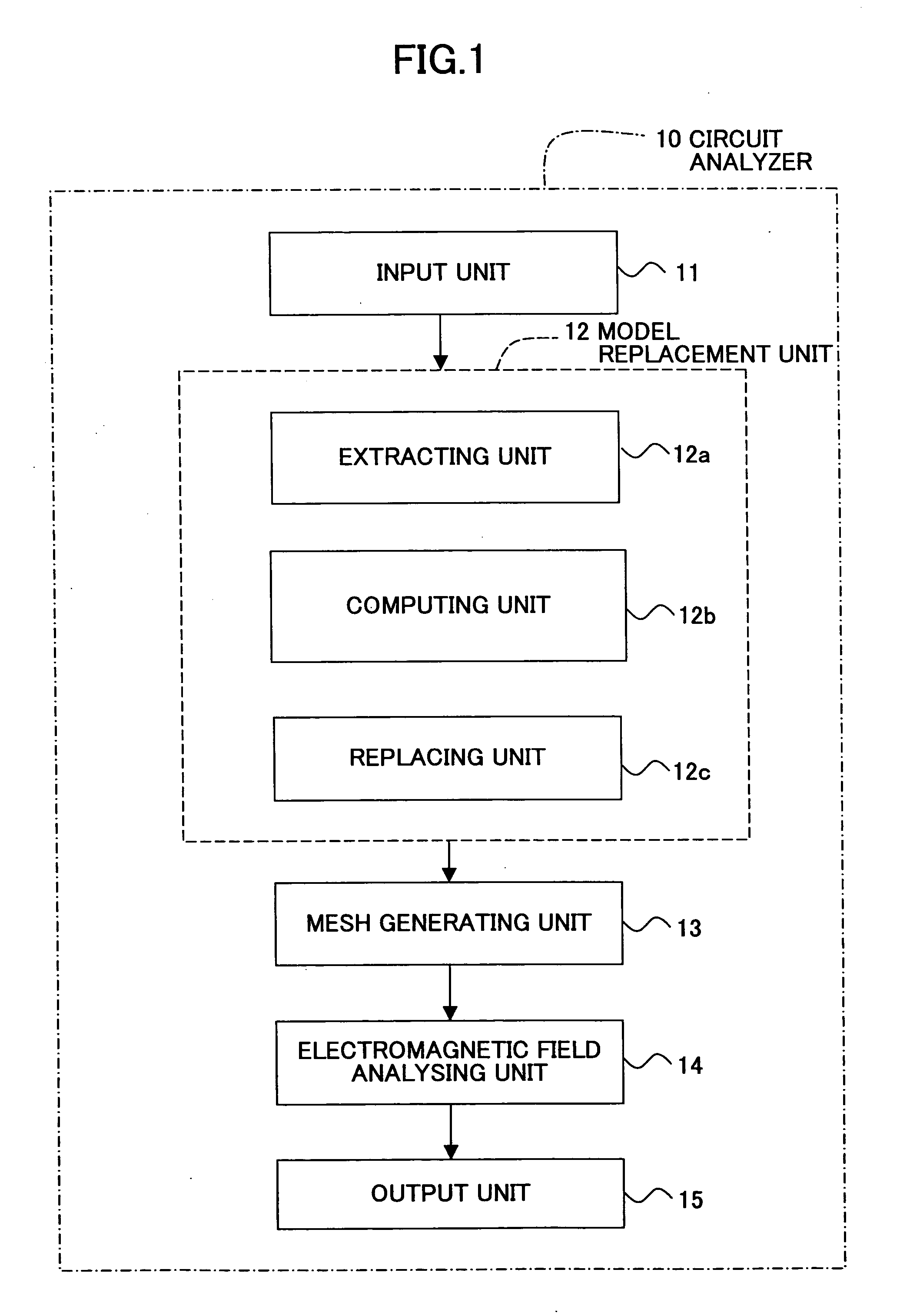
[0025]FIG. 1 is a block diagram showing the functional structure of a circuit analyzer according to an embodiment. Referring to FIG. 1, the circuit analyzer 10 according to an embodiment includes an input unit 11 for inputting 3 dimensional data of an electric circuit apparatus, a model replacement unit 12 for replacing based on the 3 dimensional data a region that affects to a small extent or does not affect the transmission characteristics of the electric circuit apparatus with a model in which the number of mesh units to be generated is reduced. The circuit analyzer 10 further includes a mesh generating unit 13 for meshing the electric circuit apparatus based on the replaced 3 dimensional data, an electromagnetic field analyzing unit 14 for analyzing the transmission characteristics of the signal wiring of the electric circuit apparatus, and an output unit 15 for outputtin...


PUM


Abstract

A method of analyzing transmission characteristics of signal wiring in a circuit apparatus including the signal wiring and insulative layer is disclosed. The transmission characteristics are analyzed by dividing the circuit apparatus with a mesh and applying electromagnetic analysis method to each unit of the mesh. The method includes the steps of: extracting signal wiring data from 3 dimensional data of the circuit apparatus; designating a sparse mesh region in which the mesh can be made sparse based on the extracted signal wiring data and the 3 dimensional data; and generating sparse mesh in the sparse mesh region. Since the sparse mesh region is designated based on the sizes of the signal wiring and the insulative layer and on the electric properties of the insulative layer, a region that affects the transmission characteristics of the signal wiring only to a small extent can be designated as the sparse mesh region.

Description

BACKGROUND OF THE INVENTION [0001] 1. Field of the Invention [0002] The present invention generally relates to a method of and an apparatus for analyzing a circuit, and more particularly, to a method of and apparatus for analyzing the transmission characteristics of a circuit apparatus such as an electric circuit, an electronic circuit, and an integrated circuit. [0003] 2. Description of the Related Art [0004] Recently, the data transmission speed of an image processing apparatus and a communication apparatus, for example, is increasing even to more that 1 GHz. In the case of such a high frequency signal, the transmission characteristics of a signal may be considerably different from that of a low frequency signals. For example, if a transmission channel has a perpendicular corner, current density at the inside of the corner becomes greater than that of the outside of the corner. In addition, since a reflection factor increases, current loss also increases. In such a case, if the si...

Claims


Application Information

Patent Timeline
Patent Type & Authority Applications(United States)
IPC IPC(8): G06F17/50
CPCG06F17/5018G06F30/23
Inventor YAMAZAKI, MANABU
Owner FUJITSU LTD
Learn More