
System for registering, locating, and identifying network equipment

Inactive Publication Date: 2005-11-03
OPSWARE
View PDF4 Cites 101 Cited by
  • Summary
  • Abstract
  • Description
  • Claims
  • Application Information

AI Technical Summary

Benefits of technology

[0014] As a further feature of the present invention, the information stored in the central database provides a link between the logical IP name of a server and the physical location of that server to assist a technician in locating a particular server in the data center. Upon determining that a particular server requires attention, the present system queries the central database and displays to a technician the location and unique identifier (first-displayed) information associated with the server. The technician then proceeds to the server in question, based on the displayed location information. As an additional feature, the present invention permits the positive verification of the identity of the server at hand. In this mode, the hand-held controller is utilized to read the unique identifier affixed to the coupler attached to the server and displays the result of the scan to the technician. If the controller-displayed identifier matches the first-displayed identifier information, the technician can be assured that the server at issue has been located.

Problems solved by technology

However, unlike personal computers, servers often lack a keyboard or a display with which to query and identify the particular server.
Furthermore, serial numbers may be located inside the server housing and therefore be difficult to access or view by a technician; or may be on the motherboard or the network interface card, which may be replaceable during the life of the server.
Therefore, when operational software, a user, or data center personnel detect a possible error or malfunction associated with a server, the problematic server can often only be identified by its logical server name, which generally has no nexus to the server's physical location or identification in the data center.
Even when the technician locates what he or she believes to be the server in question, there is no way to know for certain by looking at the server that the server at hand corresponds to the logical server name the technician is supposed to service.
However, charts and maps can be unreliable for correctly identifying a particular server because the association between the logical name of the server and the manually-maintained chart or map could either be out of date or could have been incorrectly entered during creation of the chart or map.
Servers are often added to the data center, moved around the data center, or swapped with other servers without the chart or map being updated, and data center personnel can inadvertently transpose address numbers when logging the initial or changed location of servers.
Not only is this process prone to error and the misentry of information, it is also time-consuming and may actually delay bringing a server online, especially in rapidly growing server farms that may experience server additions and changes numbering in the hundreds every day.
For all of these reasons, actually locating the server at issue for purposes of diagnosing and resolving a server problem or performing scheduled maintenance or determining real-time or historical usage can be a difficult, time-consuming, and imprecise task.
As a result, in some instances, servers become “lost” among the thousands of servers in a data center.
In other words, the data center personnel have no means whereby they can identify these sought servers in the data center.
These lost servers can be monitoring servers, application servers, or database servers—the loss of any of which can be damaging to the data center and the users that are attempting to access the resources of the data center through its various servers.
Furthermore, even when a data center technician locates what he or she believes to be the problem server, no means presently exist by merely looking at the server to verify that the server corresponds to the logical name of the server at issue.
Even if the logical server name is affixed to the exterior of the server, the ease by which logical server names may be changed causes an uncertainty as to whether the external markings on the server are both up to date and accurate.
Therefore, if the technician begins working on a server without first verifying that it has the targeted logical server name, the data center runs the risk of taking down an active, functioning server and thereby severing the active connection of one or more users and potentially crashing an entire Internet web site.
Furthermore, in addition to severing the connection to potentially thousands of users, taking down the wrong server could result in the irrecoverable loss of important data that is being transmitted through the server.

Method used


Image

  • System for registering, locating, and identifying network equipment
  • System for registering, locating, and identifying network equipment
  • System for registering, locating, and identifying network equipment

Examples


Embodiment Construction

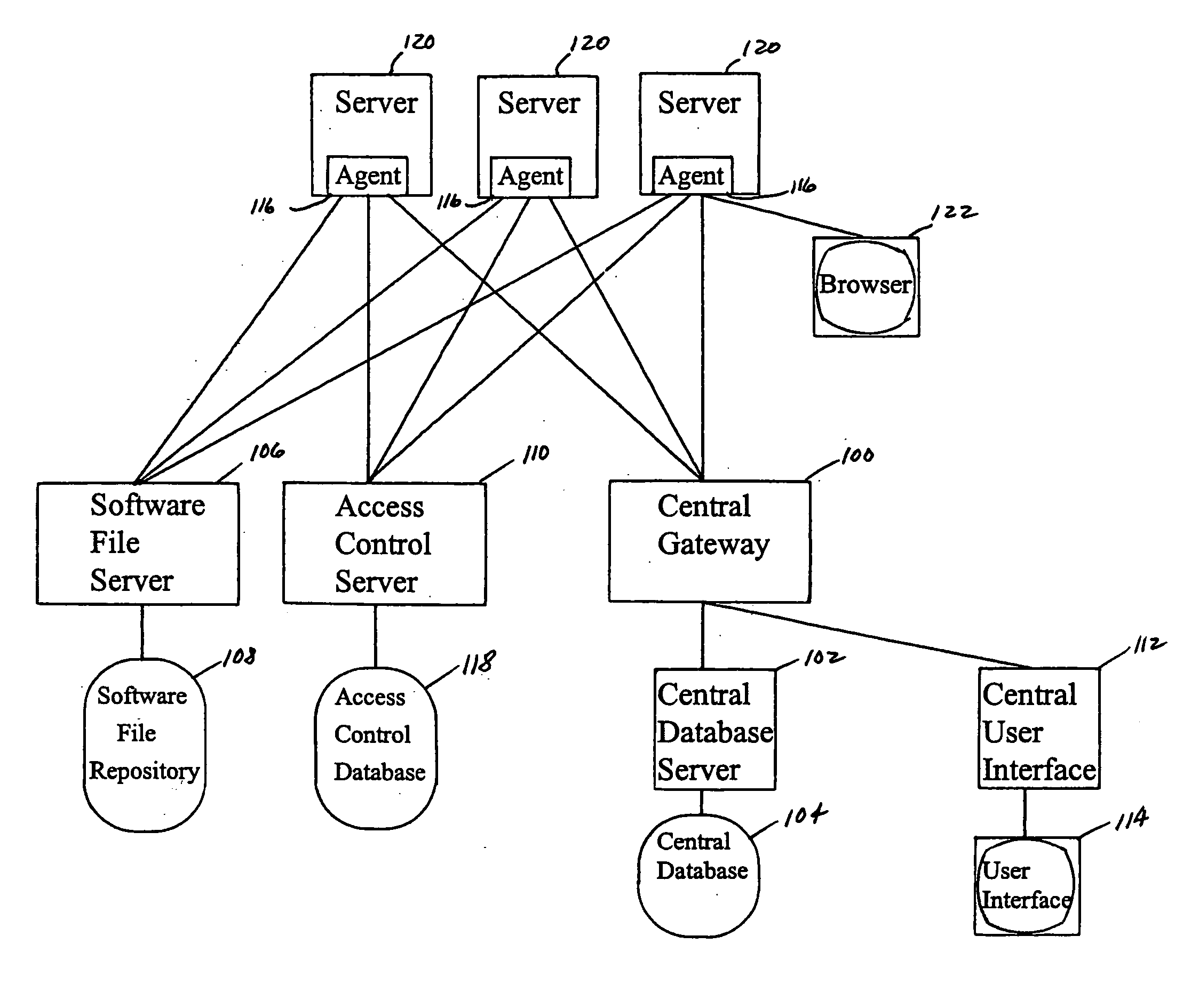
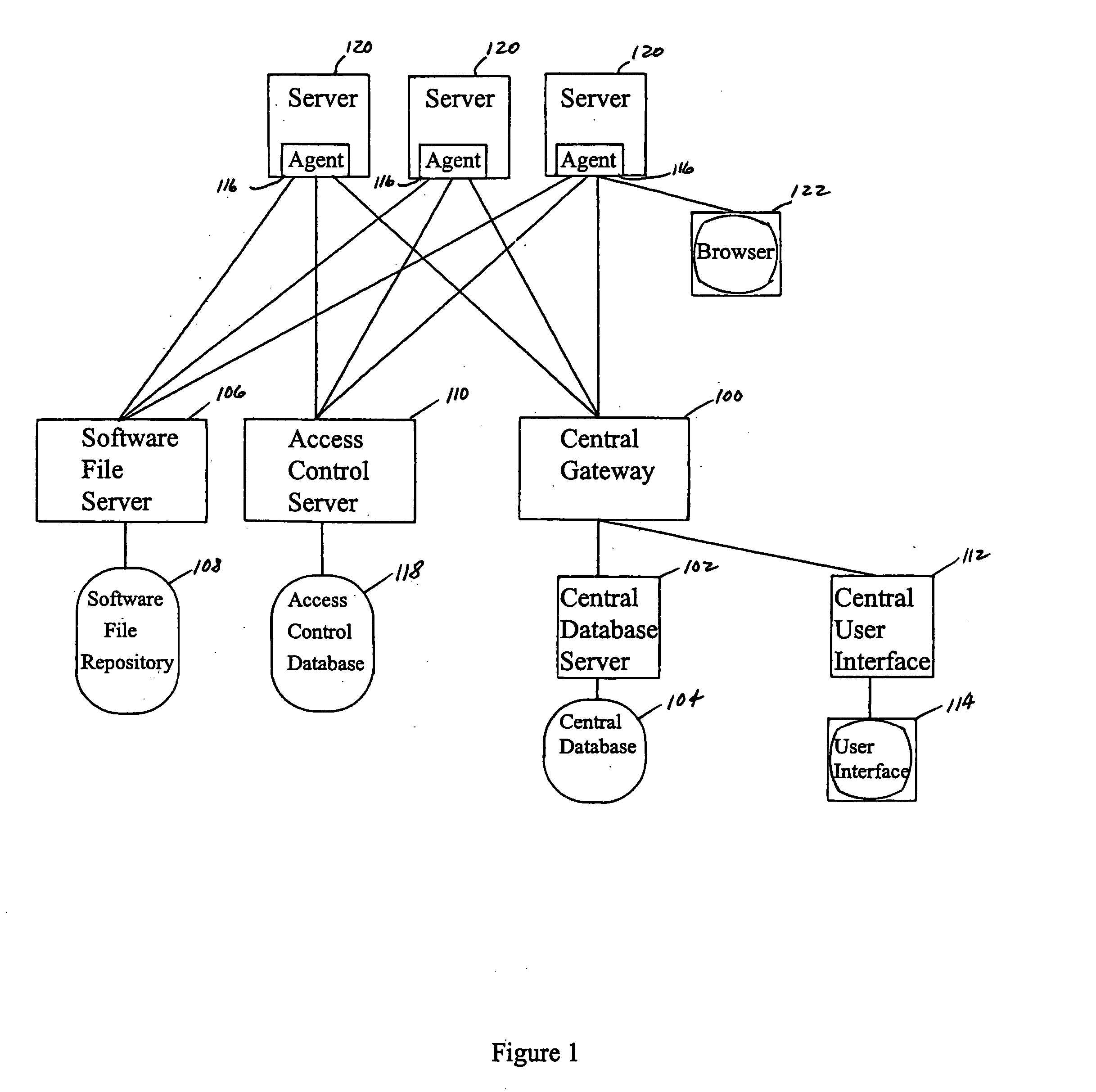
[0032] Referring now to FIG. 1, there is illustrated a block representation of an exemplary logical server network within which the present invention functions. The structure of the network as displayed in FIG. 1 is representative of the multi-layered server / database architecture that is supported by the present invention. An access-control server called the central gateway 100 is the interface through which servers, users, and applications communicate and access software and information on the network. As the primary control processor of the network, the central gateway 100 talks to and is talked to by each of the elements of the network. For example, a remote user accessing the network through one of the servers 120 and requesting information stored on a central database 104 managed by the central database server 102 will have the request routed through the central gateway 100 for clearance. An approved request may proceed to access information through the central database server ...


PUM


Abstract

The present invention is directed toward providing a system for registering, locating, and identifying network servers within a data center containing many such servers. Parallel and serial port couplers with an erasable, programable read-only memory are encoded with a unique ID number, and a label with a bar code corresponding to the ID number is affixed to each coupler. A server to be installed in a data center has an encoded coupler attached to one of its communication ports, and information related to that particular server is stored in a system database. Upon encountering a problem with a network server, the system displays the logical name of the server at issue. The location and identification information for the server are retrieved from the system database and displayed to a technician responsible for the server at issue. Using the displayed location information, the technician reads the label on the coupler connected to the suspected server and verifies that the ID number on the coupler matches the ID number displayed for the server requiring service.

Description

CROSS-REFERENCE TO RELATED APPLICATION [0001] This application is related to copending, commonly assigned United States nonprovisional application Ser. No. 09 / 632,796 filed Aug. 4, 2000, the disclosure of which is incorporated herein by reference.BACKGROUND OF THE INVENTION [0002] 1. Field of the Invention [0003] The present invention relates generally to identifying equipment in a data center, and more particularly, to registering, locating, and identifying individual network servers among a plurality of servers maintained within a large data center. [0004] 2. Description of the Related Art [0005] Early data processing services were provided by technically focused data centers which were physically proximate to the respective non-technical users of the data centers. Gradually, communication networks were established whereby users physically remote from the data center could be connected to the data center through hard-wired telephone lines and coaxial cables to access the resources...

Claims


Application Information

Patent Timeline
IPC IPC(8): H04L29/06H04L29/08H04L29/12
CPCH04L29/06H04L29/12009H04L69/329H04L61/35H04L67/18H04L29/12783H04L61/00H04L67/52H04L9/40
Inventor DAY, ROBERTLEVASSEUR, JOSHSUORSA, RAYMOND
Owner OPSWARE
Learn More