
Realtime computer assisted leak detection/location reporting and inventory loss monitoring system of pipeline network systems

a pipeline network and computer assisted technology, applied in fluid tightness measurement, instruments, nuclear elements, etc., can solve the problems of slow response technique of leak detection method, inability to detect leaks in real time, and inability to accurately predict leaks, etc., to achieve fast response time

Active Publication Date: 2005-11-03
KINGSLEY E ABHULIMEN +1
View PDF8 Cites 143 Cited by
  • Summary
  • Abstract
  • Description
  • Claims
  • Application Information

AI Technical Summary

Benefits of technology

[0015] The problems stated above, as well as other related problems of the prior art, are solved by the present invention, which is directed towards a software based leak detection system for pipeline leak detection and commodity release assessment, monitoring and control. -The present invention may be implemented by a computer assisted feedback system that achieves a fast response time, has no false alarm thresholds and has robust attributes, and which can analyze any kind of pipeline network configuration and fluid system.
[0016] The present invention is an online, web-based leak detection and inventory loss information management system that allows users the flexibility to assess information and interact with the pipeline network system to track leaks or inventory loss in any pipeline system, enhanced by use of security features like enhanced web-based encryption capability with a backup failed server platform.
[0017] The present invention can detect, assess and track leaks and inventory loss in pipeline network systems and can trigger an alarm to operators or users through a faxmodem, a web modem or voice modem in any part of the world accurately with a response time of less than a minute.

Problems solved by technology

Most conventional pipeline leak detection systems have failed in terms of response time, sensitivity, robustness and cost.
The existence of flow transients makes this method for leak detection a slow response technique, since it is necessary to either average flow over a long time period to filter out the effect of line pack changes due to transients.
For long transmission pipelines, the response time is usually very long.
Such long response time is unsatisfactory, and has the additional problem of significant data loss during the averaging time.
Pressure surges or operational changes can mask leaks if they are positive or cause false alarms if they are negative.
The major draw back to this model is the cost of installing the software and instrumentation.
Another draw back is the incidence of false alarms due to fluctuating threshold setting, model complexity and poor instrumentation.
Automatic threshold adjustment to optimize the sensitivity / false alarm / response time trade off and various means of coping with data problems would reduce the incidence of false alarms, but significantly increase the cost.
Current thresholds of false alarms reported by operators of most commonly used conventional leak detection systems create serious concerns for the need of more robust and optimal leak detection systems.
Moreover, the slow level of response time and false alarm thresholds have led to serious revenue loss translating in millions of dollars in some cases, resulting from commodity, operational and asset lost, couple with penalties for spillage to the environment and lost man hours.
The '633 Application acknowledges that multiple transients on the pipeline from normal operating procedures can produce pressure disturbances (similar to an expansion wave generated by leak event), which are located on the monitored segment of pipeline and thus cause false leak alarms.
The '633 Application further acknowledge that previous techniques such as moving average, repetitive filter, dynamic threshold and band pass filters have only been successful in removing a certain type of noise, but has little effect on other types of transient noise such as pumps, compressors and valve operation, which produce signals with amplitudes similar to the amplitudes of signals produced by leaks, which has led to a high false alarm rate and reduced sensitivity.
Due to the length of the wave front and other factors, an uncertainty in the time tag between monitors occur, which in the past has limited leak location accuracy to typically ±500 or more meters out of 10,000 meters.
This has led to the inability to accurately locate leaks.

Method used


Image

  • Realtime computer assisted leak detection/location reporting and inventory loss monitoring system of pipeline network systems
  • Realtime computer assisted leak detection/location reporting and inventory loss monitoring system of pipeline network systems
  • Realtime computer assisted leak detection/location reporting and inventory loss monitoring system of pipeline network systems

Examples


Embodiment Construction

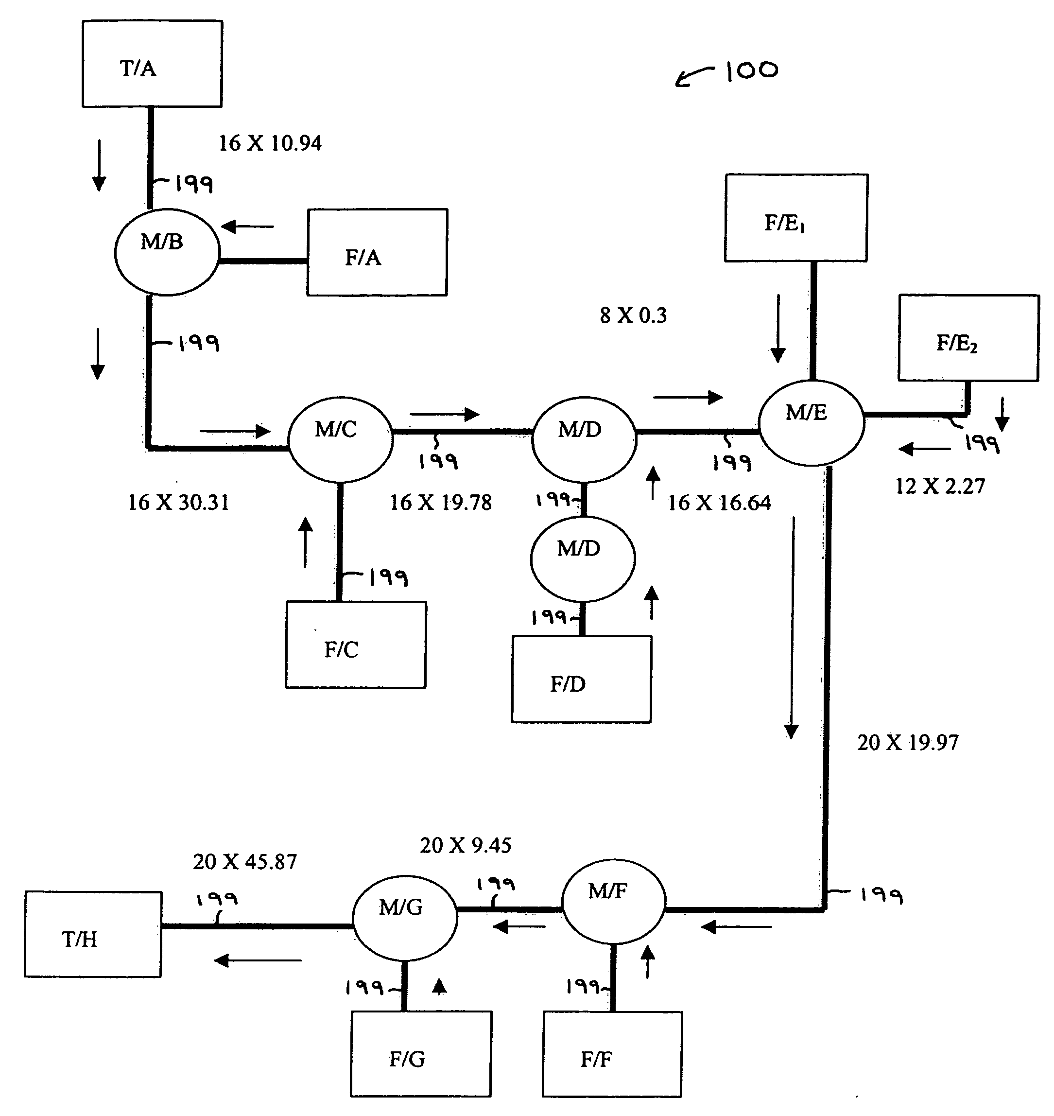
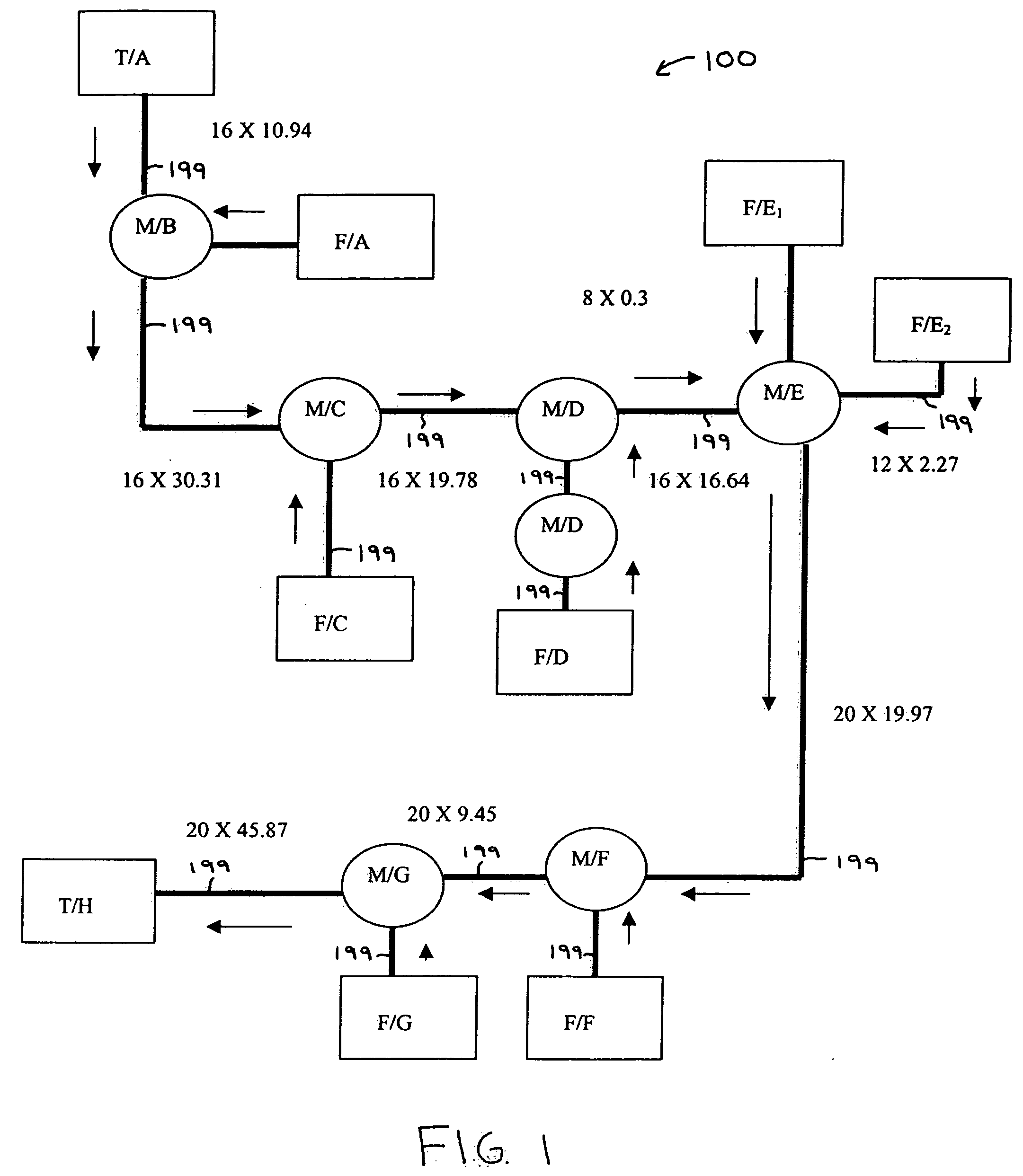
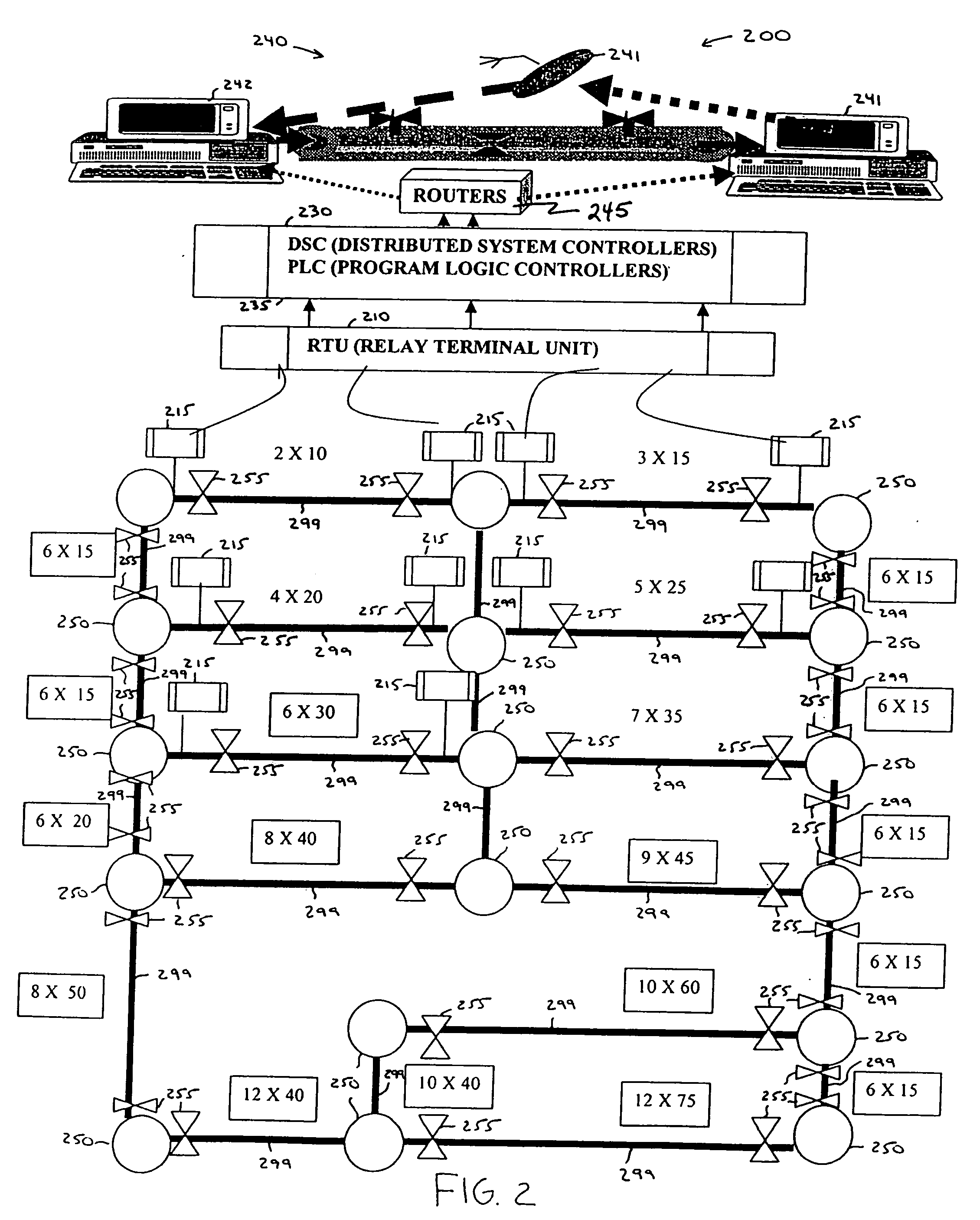
[0058] The present invention is directed to a Real-Time Computer Assisted Leak Detection / Location Reporting and Inventory Loss Monitoring System. It is to be appreciated that the present invention may be employed for any type of pipeline system, including single pipeline systems and complex pipeline systems. The pipeline system may be used to transports, e.g., liquids and / or gases. The liquids may include, but are limited to, petroleum-based liquids, water, blood, and so forth.

[0059] It is to be understood that the present invention may be implemented in various forms of hardware, software, firmware, special purpose processors, or a combination thereof. Preferably, the present invention is implemented as a combination of hardware and software. Moreover, the software is preferably implemented as an application program tangibly embodied on a program storage device. The application program may be uploaded to, and executed by, a machine comprising any suitable architecture. Preferably,...


PUM

PropertyMeasurementUnit
axial distanceaaaaaaaaaa
Liapunov Stability Theoryaaaaaaaaaa
sonic velocityaaaaaaaaaa

Abstract

There is provided a method for detecting and locating leaks in a pipeline network in real-time. A flow model is provided that characterizes flow behavior for at least one of steady and unsteady states respectively corresponding to an absence and a presence of model leaks in the pipeline network, the flow model including a leaking factor kL. A deterministic model is provided to evaluate at least one of a leak status and a no leak status relating to the pipeline network using deterministic criteria. The deterministic criteria is based on a Liapunov Stability Theory. A deviation matrix is constructed based on the flow model and the deterministic model to generate eigenvalues. A leak alarm is generated when at least one of the eigenvalues is less than a predetermined value.

Description

BACKGROUND OF THE INVENTION [0001] 1. Field of the Invention [0002] The present invention generally relates to detection and monitoring systems and, more particularly, to a real-time method and system for detecting leaks and inventory loss and for managing information corresponding thereto. The present invention may be employed with respect to, for example, gas and liquid pipeline network systems, storage tanks of process systems, blood vessels and stroke management. [0003] 2. Background of the Invention [0004] Most conventional pipeline leak detection systems have failed in terms of response time, sensitivity, robustness and cost. Pipeline leaks can be detected by observation of the external effects of the spill, or by monitoring and analysis of the internal hydraulics of the pipeline. One of the objectives of a pipeline leak detection system is to alert operators so that the size of the spill can be limited, which argues for speedy detection as well as reliability and sensitivity....

Claims


Application Information

Patent Timeline
Patent Type & Authority Applications(United States)
IPC IPC(8): F17D5/02G01F1/66G01M3/00G01M3/04G01M3/28G01N11/00G21C17/017
CPCF17D5/02G01M3/2815G01M3/2807
Inventor ABHULIMEN, KINGSLEY E.SUSU, ALFRED A.
Owner KINGSLEY E ABHULIMEN
Learn More