Powered patch panel

a patch panel and power supply technology, applied in the field of communication components, can solve problems such as the need for timely response, and achieve the effects of facilitating monitoring the state, reducing the power consumption of the active jack, and enhancing the scope of patch panel managemen

Inactive Publication Date: 2005-11-03
PANDUIT
View PDF99 Cites 166 Cited by
  • Summary
  • Abstract
  • Description
  • Claims
  • Application Information

AI Technical Summary

Benefits of technology

[0008] According to one embodiment of the present invention, the active jack is an electronic element that requires a source of DC power which can be obtained from Power Supplying Equipment (PSE) such as an IEEE 802.3AF compliant source. Such sources are deployed in networks as the source of DC power for an attached powered device (PD) such as a VoIP telephone that receives power according to a power-over-network scheme. According to some embodiments of the present invention, the power consumption of the active jack is minimal, with the remaining power forwarded to a powered device (PD) if one is connected.
[0009] There are several methods of supplying the active jacks with DC power. According to one embodiment of the present invention, PSE equipment such as an Ethernet switch or IP router is used. According to another embodiment a patch panel or mid-span patch panel can be used. When a patch panel is equipped with active jacks, a managed structure cable PSE system is obtained. The scope of management that a patch panel has can be enhanced if an active jack is used between the patch panel and the end device.
[0010] Current methods of cable plant management and security rely on having the state of the horizontal cable system and/or patch panels remain fairly constant. Further, if changes occur it is required that they are well documented and manually entered in the security/management system database. According to one embodiment of the present invention, use of active jacks facilitates monitoring the state of

Problems solved by technology

Issues with documenting and managing LANs have likewise increased the need for timely response when connectivity problems arise.
This has largely been due

Method used


Image

  • Powered patch panel
  • Powered patch panel
  • Powered patch panel

Examples


Embodiment Construction

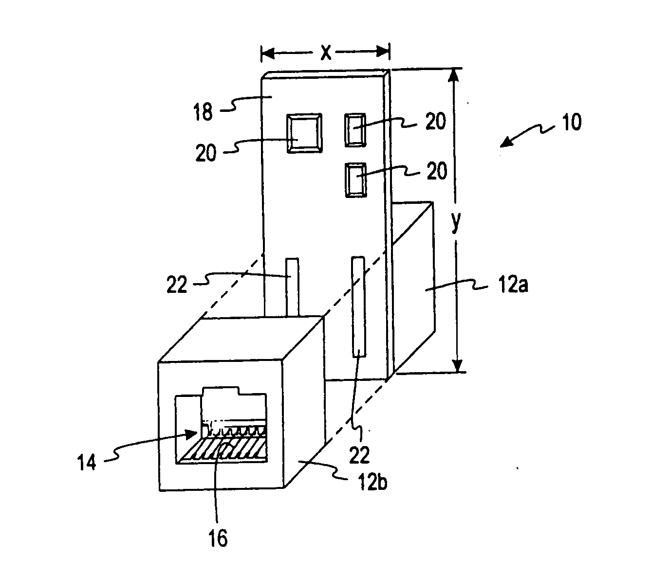
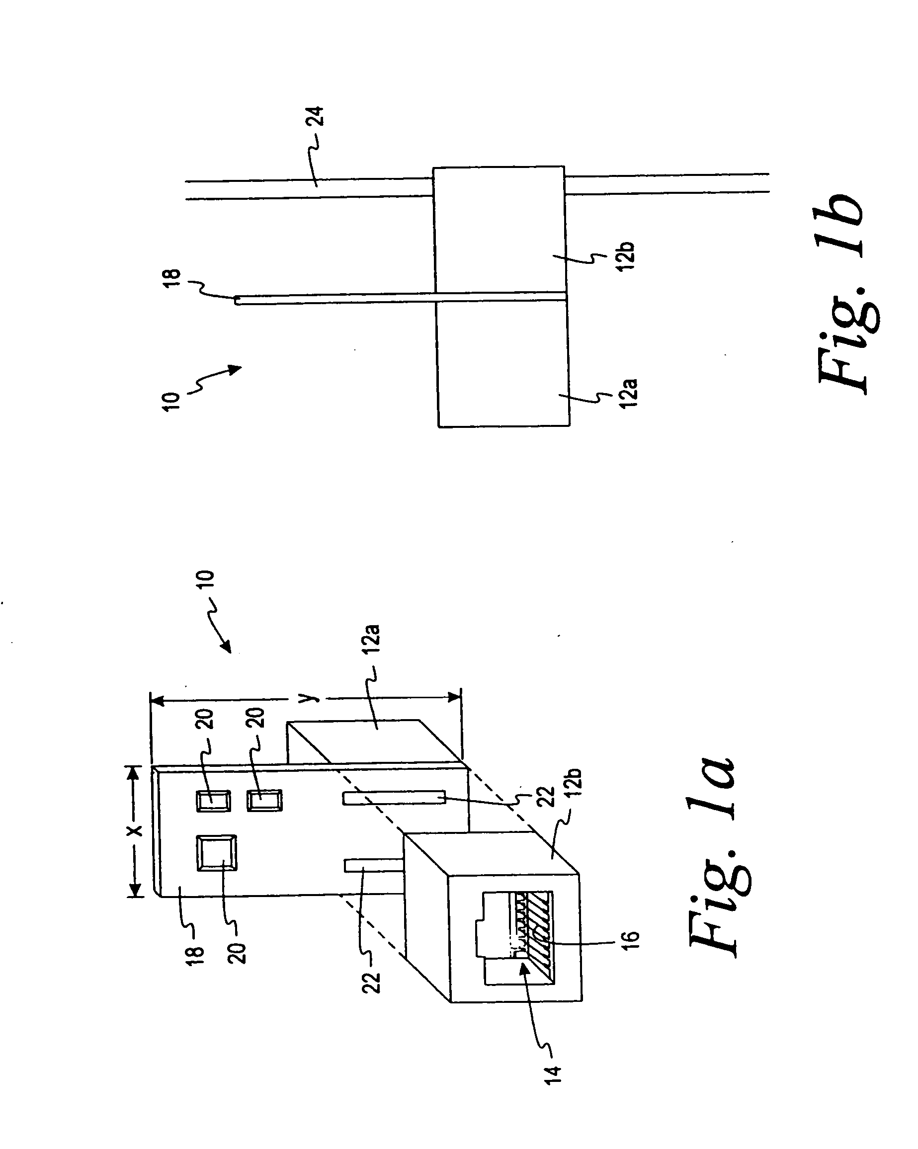
[0039] Referring now to the drawings, and initially to FIG. 1a, an isometric construction view of an active jack 10 is shown. The active jack 10 comprises two housings 12a and 12b which can form plug receiving openings 14 as shown in the drawing for the housing 12b. According to an alternative embodiment of the present invention, one connector of the active jack 10 is a pug and the other connector is an insulation displacement connector (IDC). The housings 12a and 12b may be of a type used for communication connectors as described more fully in U.S. Pat. No. 6,371,793, “Low Crosstalk Modular Communication Connector,” by Doorhy et al., issued Apr. 16, 2002 which is incorporated herein in its entirety by reference. Mounted within the plug receiving opening are a plurality of conductors 16 which form a resilient contact with a communications plug when the plug is connected to the active jack 10. The conductors 16 are led through the housing of the active jack 10 to make contact with th...


PUM


Abstract

A powered communications patch panel is adapted to power network devices connected to the communications patch panel. Power is supplied to the network devices by the powered communications patch panel over the communication cabling. The powered communications patch panel may be provided with a management port to allow remote management of the patch panel via a network connection. Multiple management ports may be provided, allowing patch panels to be connected to one another in a daisy-chain configuration.

Description

CROSS-REFERENCE TO RELATED APPLICATIONS [0001] This application claims priority to and incorporates by reference in its entirety U.S. Provisional Application Ser. No. 60 / 567,765, attorney reference number LCB464, entitled “Powered Patch Panel,” filed on May 3, 2004.FIELD OF THE INVENTION [0002] This invention is directed generally to communications components and more specifically is directed to systems and methods for managing communications networks using active jacks. BACKGROUND OF THE INVENTION [0003] The use of a local area network (LAN) to serve a wide range of communication needs has continued to escalate, with networks growing larger and denser. Issues with documenting and managing LANs have likewise increased the need for timely response when connectivity problems arise. This is even more important with the advent of voice over internet protocol (VoIP) replacing the function of the traditional phone network, but now operating over the same LAN as data services. Local area n...

Claims


Application Information

Patent Timeline
IPC IPC(8): H01R13/60H04M19/00H04Q1/14
CPCH04Q1/14H04Q2201/802H04Q1/03H04Q1/136H04Q1/035
Inventor NORDIN, RONALD A.BOLOURI-SARANSAR, MASUDDOORHY, MICHAEL V.
Owner PANDUIT
Why Eureka
Try Eureka