Steering column device

Active Publication Date: 2005-11-03
NSK LTD
View PDF8 Cites 10 Cited by
  • Summary
  • Abstract
  • Description
  • Claims
  • Application Information

AI Technical Summary

Benefits of technology

[0007] The present invention has been contrived taking the above circumstances into consideration, and an object thereof is to provide a steering column apparatus which can enhance the rigidity of a distance unit while reducing the number of the constituent parts as well as the manufacturing cost.
[0008] In order to solve the above problems, according to the present invention, there is provided a steering column apparatus comprising: a steering column provided with a body-side bracket mounted to a vehicle body strength member to have a pair of side plate portions facing each other to be extended in a vertical direction, and a substantially cylindrical distance unit for supporting a steering shaft to be rotatable therein and having a pair of pressed and expanding portions formed to be expanded by plastic working to be pressed and supported by the side plate portions of the body-side bracket; and an adjusting mechanism capable of adjusting a position of the steering column with respect to the side plate portions of the body-side bracket within a predetermined range, wherein the steering column is formed with a reinforcement portion for enhancing the clamping rigidity of the distance unit with respect to the side plate portions.
[0013] According to the present invention, the rigidity of the entire distance unit is enhanced and deflection is difficult to be caused even when a great clamping force is applied on the pressed portion.

Problems solved by technology

However, with such an arrangement, the number of the constituent parts and that of the welding steps are increased, and moreover, variable inconveniences are inevitably caused by thermal distortion, etc., at the welding.
Then, these inconveniences become conspicuous when the steering column is formed of a thin steel pipe, which results in an obstacle to reduction of the weight of the steering apparatus.

Method used


Image

  • Steering column device
  • Steering column device
  • Steering column device

Examples


Embodiment Construction

[0024] Description will be made below on an embodiment of a steering column apparatus according to the present invention.

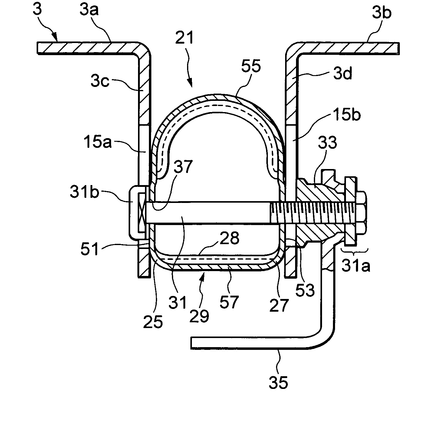
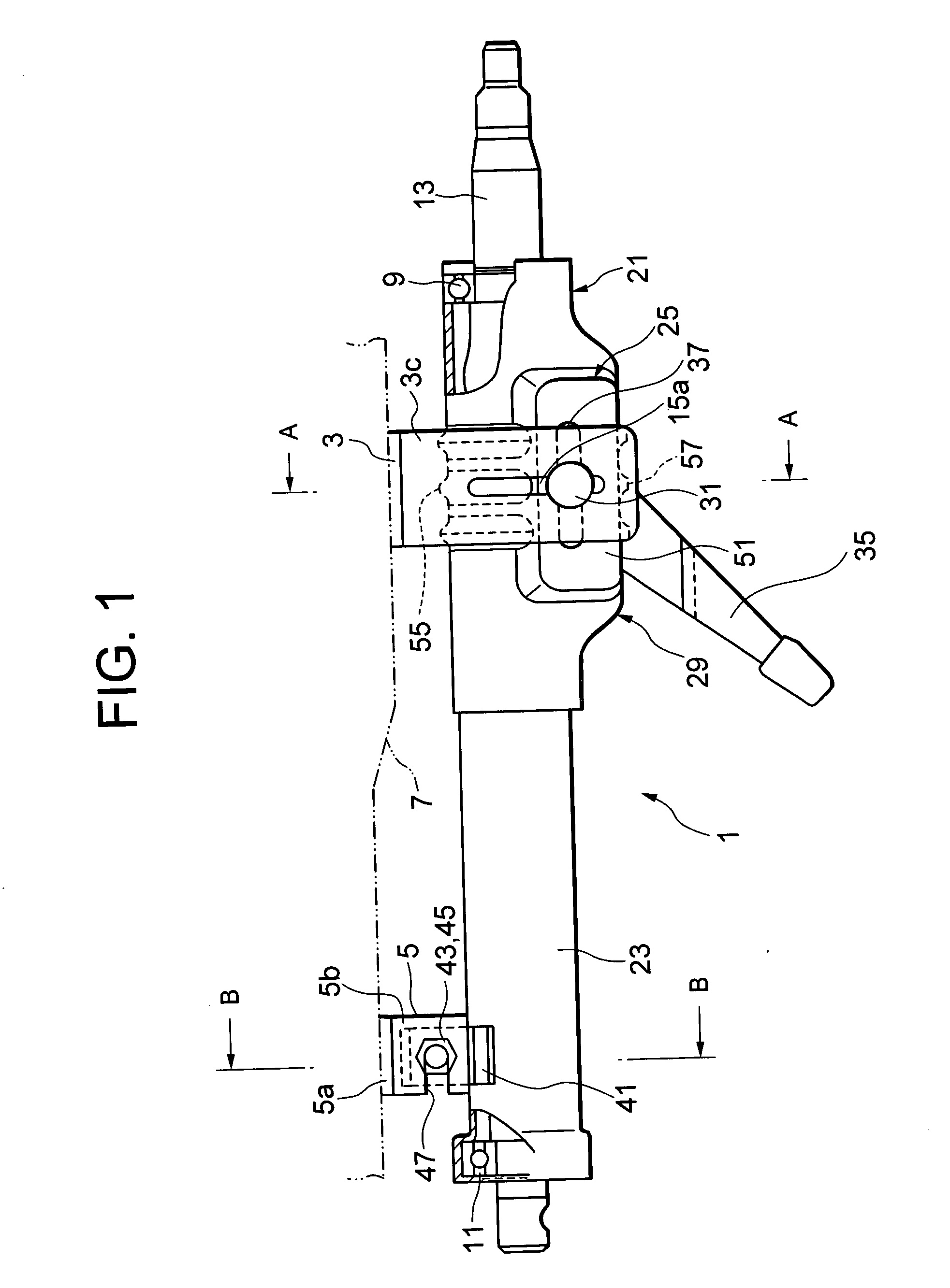
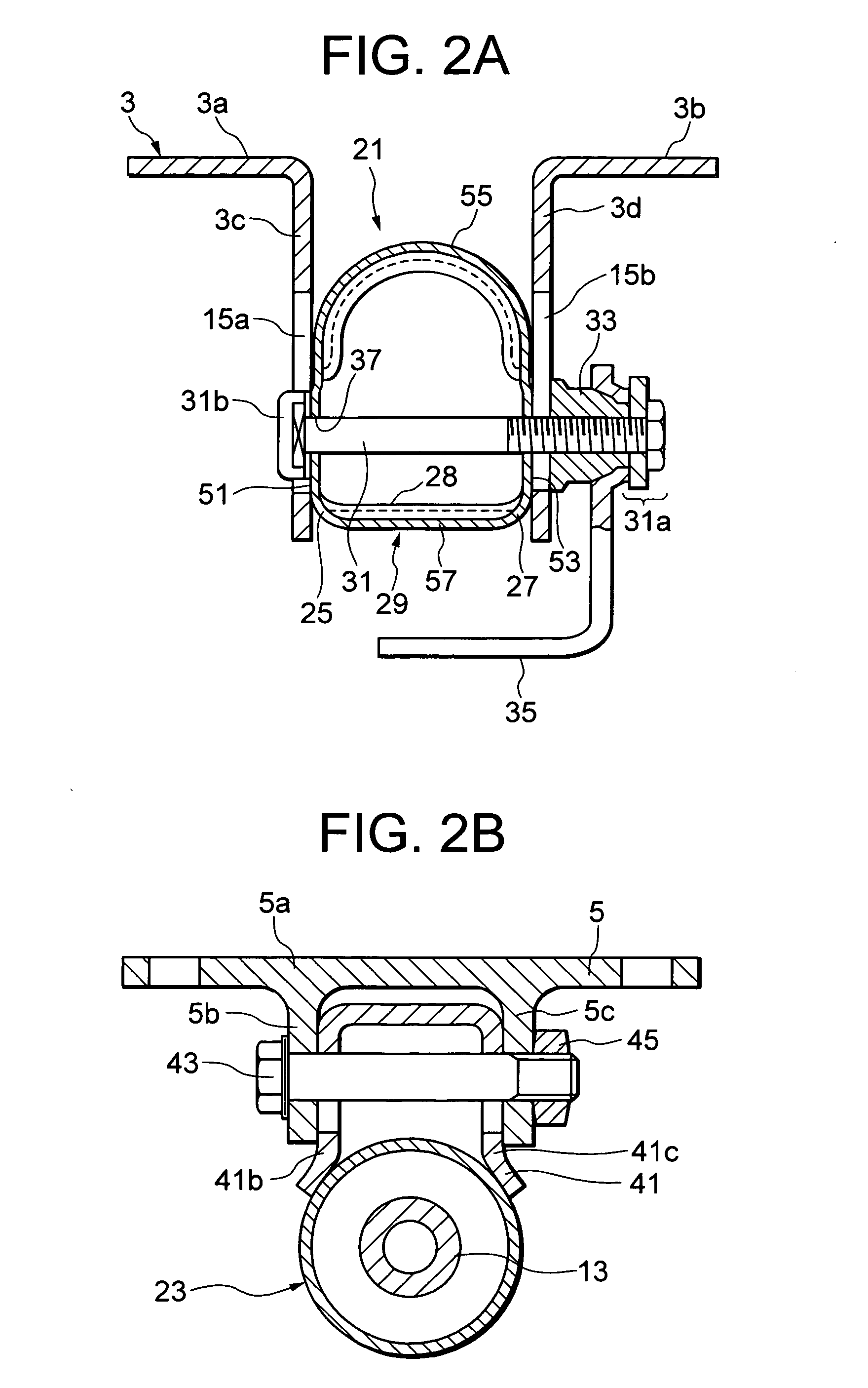
[0025]FIG. 1 is a side view of a steering column apparatus according to the first embodiment of the present invention, and FIG. 2A is an enlarged cross-sectional view taken along A-A line in FIG. 1, provided that a steering shaft 13 is omitted in FIG. 1.

[0026] The steering column 1 is attached to a vehicle body-side strength member 7 through a fixed upper bracket 3 formed of a steel plate by press-forming to serve as a vehicle body-side bracket and a pivot bracket 5 formed of alluminium alloy by die casting, so as to support an upper steering shaft (hereinafter simply called the steering shaft) 13 to be rotatable through bearings 9, 11.

[0027] The upper bracket 3 has integrally a pair of body-side mounting portions 3a, 3b having the width in the length direction of the steering shaft, and being extended symmetrically in a direction perpendicular to an extending ...


PUM


Abstract

A steering column apparatus comprising: a steering column provided with a body-side bracket mounted to a body strength member to have a pair of side plate portions opposed each other to be extended in a vertical direction, and a substantially cylindrical distance unit for supporting a steering shaft to be rotatable therein and having a pair of pressed and expanding portions formed to be expanded by plastic working to be pressed and supported by the side plate portions of the body-side bracket; and an adjusting mechanism capable of adjusting a position of the steering column with respect to the side plate portions of the body-side bracket within a predetermined range, wherein the steering column is formed with a reinforcement portion for enhancing the clamping rigidity of the distance unit with respect to the side plate portions.

Description

FIELD OF THE INVENTION [0001] The present invention relates to a steering column for constituting a steering device for a car or the like, and more specifically, to a technology for enhancing the rigidity or the like of a column distance unit for fixing the steering column on the car body. RELATED BACKGROUND ART [0002] Since a steering apparatus of a vehicle is to be used (for steering) by many and unspecific drivers, it is desirable that the position of a steering wheel is adjustable in compliance with the physique or the posture of each driver. In order to satisfy such desire, a tilt adjusting mechanism or a telescopic adjusting mechanism is widely employed not only for passenger cars, but also for freight cars. [0003] The tilt adjusting mechanism is a mechanism to adjust the position of a steering wheel in the up-and-down direction, and is constituted by a tilt pivot for rockably supporting a steering column, a tilt position fixing means for fixing the steering column at a desire...

Claims


Application Information

Patent Timeline
IPC IPC(8): B21D53/88B62D1/184
CPCB62D1/184
Inventor INOUE, KOJI
Owner NSK LTD
Why Eureka
Try Eureka