
Utility vehicle

Active Publication Date: 2019-08-01
KAWASAKI MOTORS LTD
View PDF0 Cites 1 Cited by
  • Summary
  • Abstract
  • Description
  • Claims
  • Application Information

AI Technical Summary

Benefits of technology

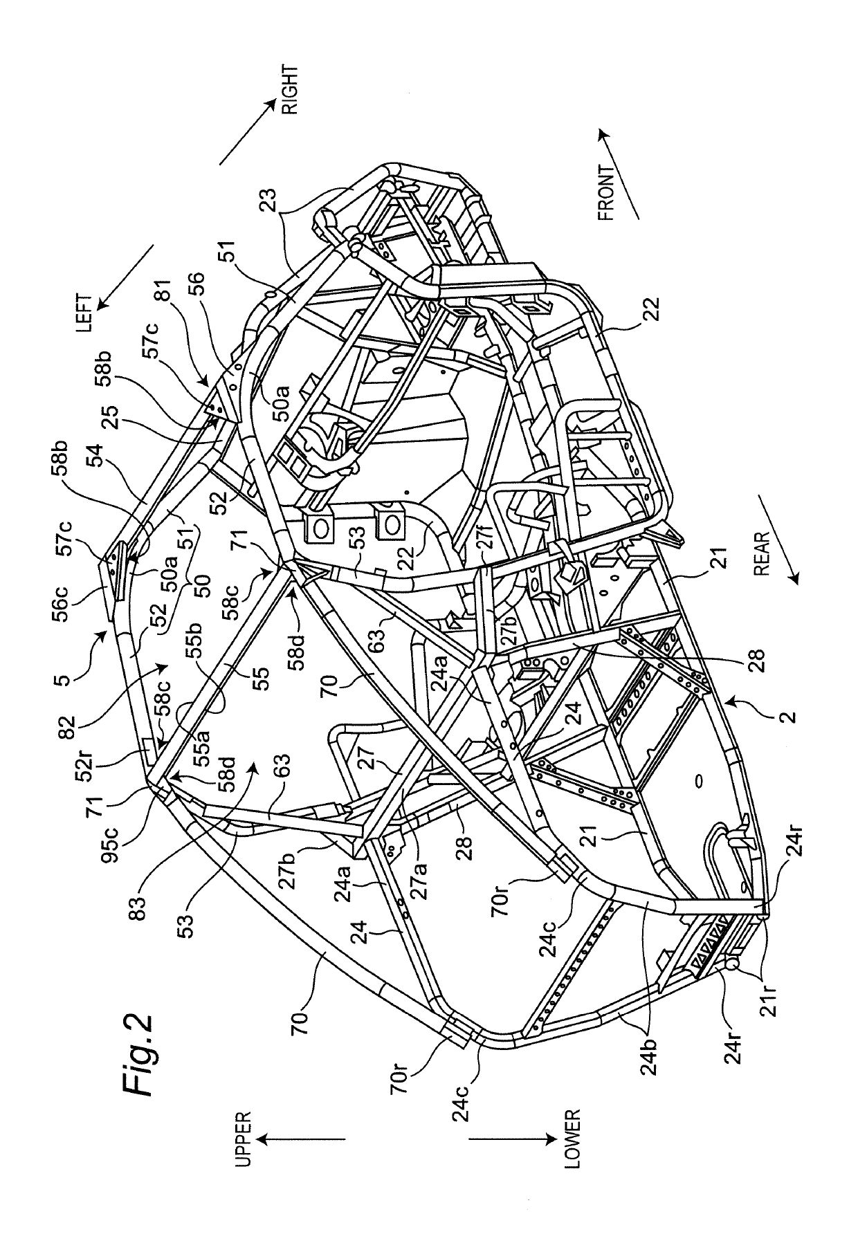
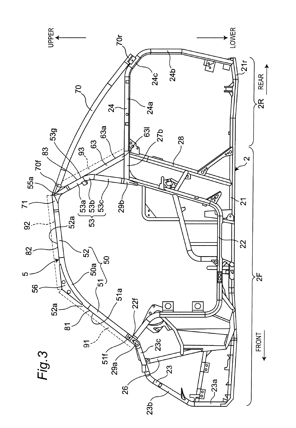
The present invention provides a utility vehicle with an enhanced R.O.P.S. that is more rigid. This is achieved by supporting the R.O.P.S. from the rear side by a rear support located between the connecting portion and the rear of the chassis. This prevents stress to accumulate on the R.O.P.S. and ensures that the vehicle body remains stable and rigid.

Problems solved by technology

Since a utility vehicle travels on rough terrains such as fields and mountains, wasteland, sloping land and the like which are not paved, the utility vehicle has a risk of unexpected falling down.

Method used


Image

  • Utility vehicle
  • Utility vehicle
  • Utility vehicle

Examples


Embodiment Construction

[0021]With reference to the attached drawings, a utility vehicle 1 according to one embodiment will be described. The utility vehicle 1 is a vehicle for mainly traveling on rough terrains such as fields and mountains, wasteland, sloping land and the like which are not paved. For convenience of explanation, a traveling direction of the utility vehicle 1 is set to be a “front side” of the utility vehicle 1 and each constitutional element, a reverse direction of the traveling direction of the utility vehicle 1 is set to be a “rear side” of the utility vehicle 1 and each constitutional element and left and right sides in a width direction of a vehicle body as viewed from an occupant are set as “left and right sides” of the utility vehicle 1 and each constitutional element.

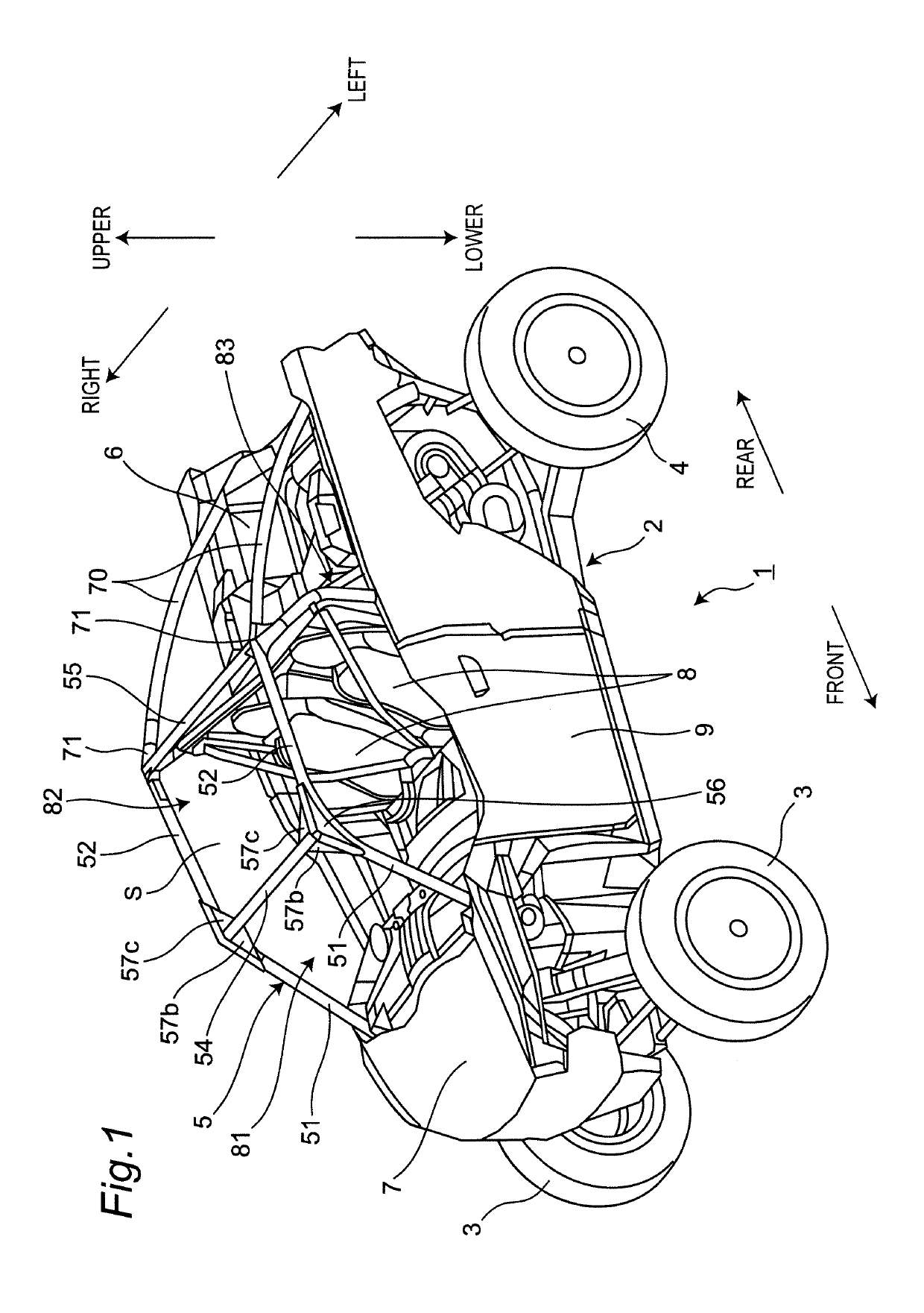
[0022]FIG. 1 is a perspective view of the utility vehicle 1 according to one embodiment of the present invention as viewed from a front left side.

[0023]As shown in FIG. 1, the utility vehicle 1 includes a chassis 2 and...


PUM


Abstract

A utility vehicle of the present invention comprises a chassis; and a R.O.P.S. provided on the chassis and surrounding a cabin, wherein the R.O.P.S. includes a pair of left and right front pillars, a pair of left and right side beams, a pair of left and right rear pillars, and a front beam and a rear beam which extend in a width direction of a vehicle body, the R.O.P.S. has a connecting portion connecting a rear end of the side beam, a side end of the rear beam and an upper end of the rear pillar, and between the connecting portion and a rear portion of the chassis, a rear support for supporting the R.O.P.S. from a rear side is disposed.

Description

BACKGROUND OF THE INVENTION1. Field of the Invention[0001]The present invention relates to a utility vehicle.2. Description of the Related Art[0002]A utility vehicle has been known that enhances the running performance on rough terrains. It is disclosed that a R.O.P.S. (Roll-Over Protective Structure) for protecting a cabin is provided on a chassis in a utility vehicle (for example, US2015 / 0259011 A1, and the like).[0003]Since a utility vehicle travels on rough terrains such as fields and mountains, wasteland, sloping land and the like which are not paved, the utility vehicle has a risk of unexpected falling down. Therefore, a utility vehicle may be provided with a R.O.P.S. to protect an occupant in case of unexpected falling down. A R.O.P.S. is constituted by a framework including, for example, four front, rear, right and left pillars, and multiple beams connecting the pillars. As rigidity of a R.O.P.S. is enhanced, deformation of the R.O.P.S. is suppressed and safety of an occupan...

Claims


Application Information

Patent Timeline
IPC IPC(8): B60R21/13B62D27/06B62D39/00
CPCB60R21/13B62D27/06B62D39/00B62D23/005B62D27/065
Inventor HISAMURA, TAKASHIHISADA, KAZUMASAKINOSHITA, MASATO
Owner KAWASAKI MOTORS LTD
Learn More