Blade coating apparatus and disk coating apparatus using the same

Inactive Publication Date: 2006-07-20
FUJIFILM HLDG CORP +1
View PDF2 Cites 0 Cited by
  • Summary
  • Abstract
  • Description
  • Claims
  • Application Information

AI Technical Summary

Benefits of technology

[0005] The coating apparatus disclosed in JP-A-63-224761 can be indeed configured in a simple structure. However, an applicator partially supported on the to-be-coated member performs application while keeping a relative distance between the downstream-side blade and the to-be-coated member. As a result, there is a defect that the to-be-coated member is limited to a belt-like member such that uncoated portions may be generated on the opposite end sides of the blades.
[0009] The invention was achieved under such circumstances. An object of the invention is to provide a blade coating apparatus and a disk coating apparatus which can apply a coating material stably in a simple apparatus configuration, to thereby prevent stripes from occurring in a coated surface.
[0012] In the blade coating apparatus, the blade-movement-direction length L of the pressure surface of the blade is set to be 10 times to 20 times as large as the thickness of the coating liquid layer, the angle α between the pressure surface and the front side surface is set to be in a range of 110°≦α≦150°, and the angle β between the pressure surface and the rear side surface is set to be in a range of 60≦β<100°. Accordingly, the blade can be formed into a sectional shape with high rigidity. The coating liquid layer applied by the blade can be made flat in terms of surface property. The thickness of the coating liquid layer can be made uniform.
[0013] When the angle α between the pressure surface and the front side surface is in a range of 110°≦α≦150°, the coating liquid is introduced into the gap (gap between the pressure surface and the to-be-coated surface) smoothly and the introduced coating liquid is pressed on the to-be-coated surface by the pressure surface with optimal pressure. When the angle β between the pressure surface and the rear side surface is in a range of 60°≦β<100°, there hardly occurs a so-called wicking phenomenon, i.e. a phenomenon that a part of the coated film is wicked up on the rear side surface of the blade immediately after the passage of the blade. Accordingly, it is possible to prevent the surface property of the coating liquid layer from being deteriorated due to the liquid wicked up on the rear side surface of the blade and then dropping down to the coated film. (2) A blade coating apparatus according to the paragraph (1), wherein the thickness of the coating liquid layer at the time of application is in a range of from 100 μm to 300 μm.
[0016] In this disk coating apparatus, a coating apparatus capable of coating in a large area is used to form at least one layer of a printing surface of a disk-like recording medium. Accordingly, it is possible to form a uniform and high-quality coating liquid layer. Thus, the printing layer (ink accepting layer) on which printing will be performed, for example, by an inkjet printer can be formed to be thick enough to provide necessary and sufficient ink acceptability.
[0017] In the blade coating apparatus and the disk coating apparatus using the blade coating apparatus according to the invention, the rigidity of the blade can be enhanced. Accordingly, the coating liquid can be applied stably with uniform pressure. As a result, stripes can be prevented from occurring in the coated surface.

Problems solved by technology

As a result, there is a defect that the to-be-coated member is limited to a belt-like member such that uncoated portions may be generated on the opposite end sides of the blades.
However, the to-be-coated member is limited to a belt-like member or a rectangular member.
When the liquid film becomes thick, there arises a problem that stripes may occur in the coated surface due to disorder of beads on the downstream side of the micro rod bar.
Accordingly, the equipment becomes so massive.
In addition, when the liquid film becomes thick, there also arises a problem that stripes may occur in the same manner as in the aforementioned substrate coating apparatus.
That is, the apparatus becomes massive.
As a result, it is difficult to ensure a good coating film surface.

Method used


Image

  • Blade coating apparatus and disk coating apparatus using the same
  • Blade coating apparatus and disk coating apparatus using the same
  • Blade coating apparatus and disk coating apparatus using the same

Examples


example 1

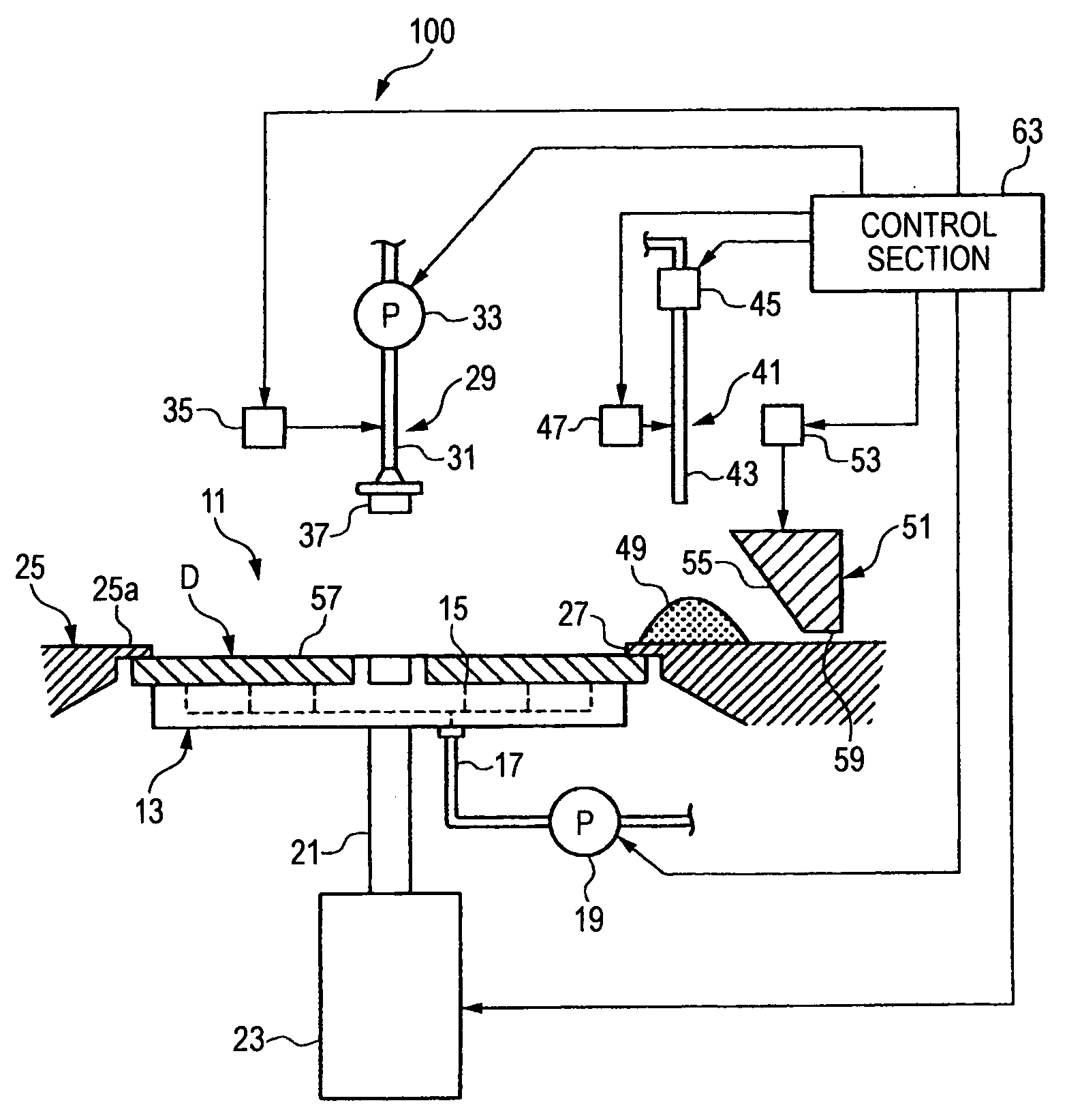
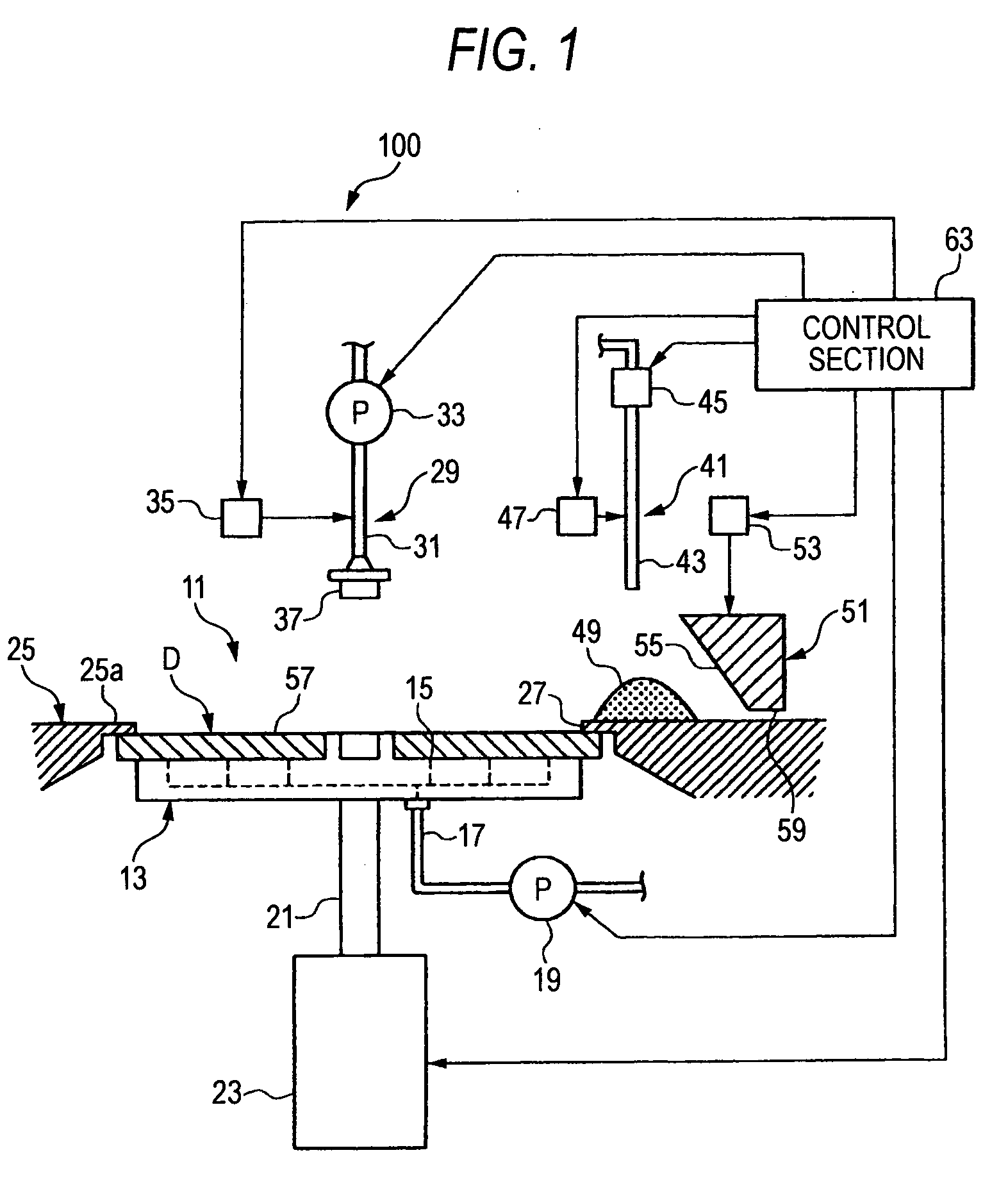
[0066] Next, Examples and Comparative Examples in each of which a coating liquid 49 was applied onto an optical disk by a blade coating apparatus having the same configuration as that in the embodiment will be described.

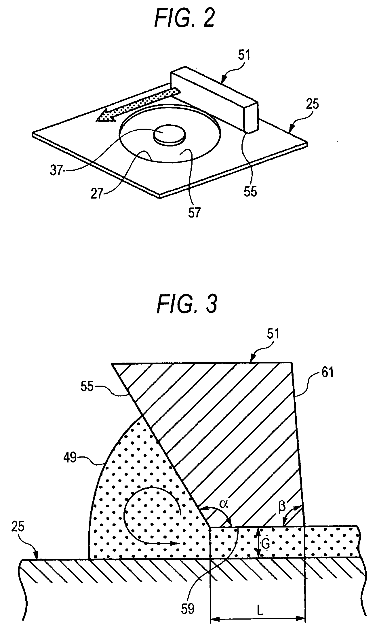
[0067] A coating liquid composed of materials shown in Table 1 for forming an accepting layer in the optical disk was used. This coating liquid was applied with a thickness of 100-200 μm on a surface of the optical disk. Incidentally, the viscosity of the coating liquid was measured by a B-type viscosimeter (Vismetron) under an environment of 25°. As a result, the viscosity of the coating liquid was 500 cP.

TABLE 1MaterialQuantityVapor deposited silica particle8.0partsIon exchanged water52.5partsPolyoxymethylene lauryl ether3.0partsAqueous solution of polyvinyl alcohol (9%)26.0partsdiethylene glycol monobutyl ether0.5partsboric acid (6%)10.0partsTotal100.0parts

[0068] Each coating apparatus for applying the coating liquid was designed so that the blade-movement-dire...


PUM


Abstract

A blade coating apparatus comprising: the mask defined herein; and the blade defined herein; wherein a section of the blade perpendicular to a longitudinal direction of the blade is shaped as: a blade-movement-direction length of a pressure surface located on a lower side of the blade and facing a surface to be coated is 10 times to 20 times as large as a thickness of the coating liquid layer at the time of application; an angle α between the pressure surface and a front side surface of the blade located in front in the blade movement direction is in a range of 110°≦α≦150°; and an angle β between the pressure surface and a rear side surface of the blade located at the rear in the blade movement direction is in a range of 60°≦β<100°.

Description

FIELD OF THE INVENTION [0001] The present invention relates to a blade coating apparatus for coating a flat substrate with a coating liquid by use of a blade, and a disk coating apparatus using the blade coating apparatus. BACKGROUND OF THE INVENTION [0002] Various proposals have been heretofore made for stably applying a liquid coating material onto a to-be-coated surface of a to-be-coated member. For example, a coating apparatus disclosed in JP-A-63-224761 includes side frames sliding on a to-be-coated member, and two blades provided to extend between the side frames so as to form a pocket for storing a coating liquid. The coating apparatus drains and applies the coating liquid from the pocket onto the to-be-coated member through a gap which is located in a lower end of one of the blades on the downstream in a movement direction. The coating apparatus has a lubrication layer forming means for forming a lubrication layer on an upper surface of the to-be-coated member on which the s...

Claims


Application Information

Patent Timeline
IPC IPC(8): B05C11/11
CPCB05C11/08G11B7/266
Inventor TAKAHASHI, SHINSUKE
Owner FUJIFILM HLDG CORP
Why Eureka
Try Eureka