
Dual sight scope system and method

Inactive Publication Date: 2005-11-03
BAE SYST ELECTRONICS SUSTAINMENT
View PDF17 Cites 65 Cited by
  • Summary
  • Abstract
  • Description
  • Claims
  • Application Information

AI Technical Summary

Benefits of technology

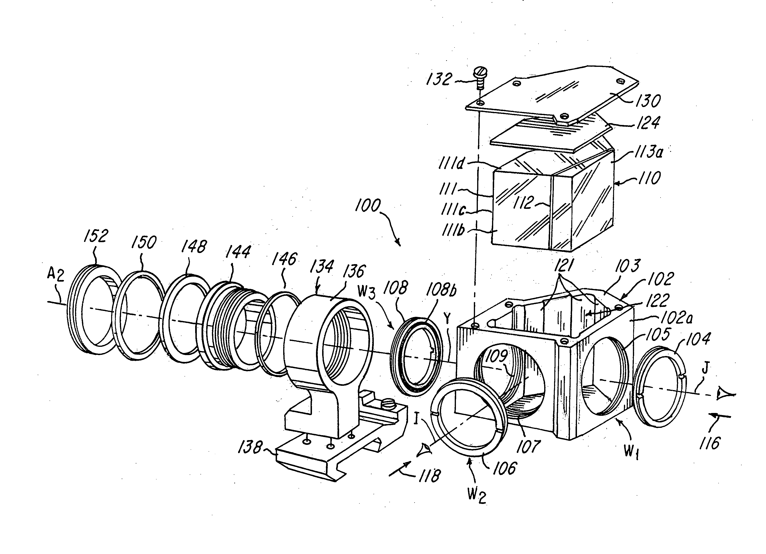
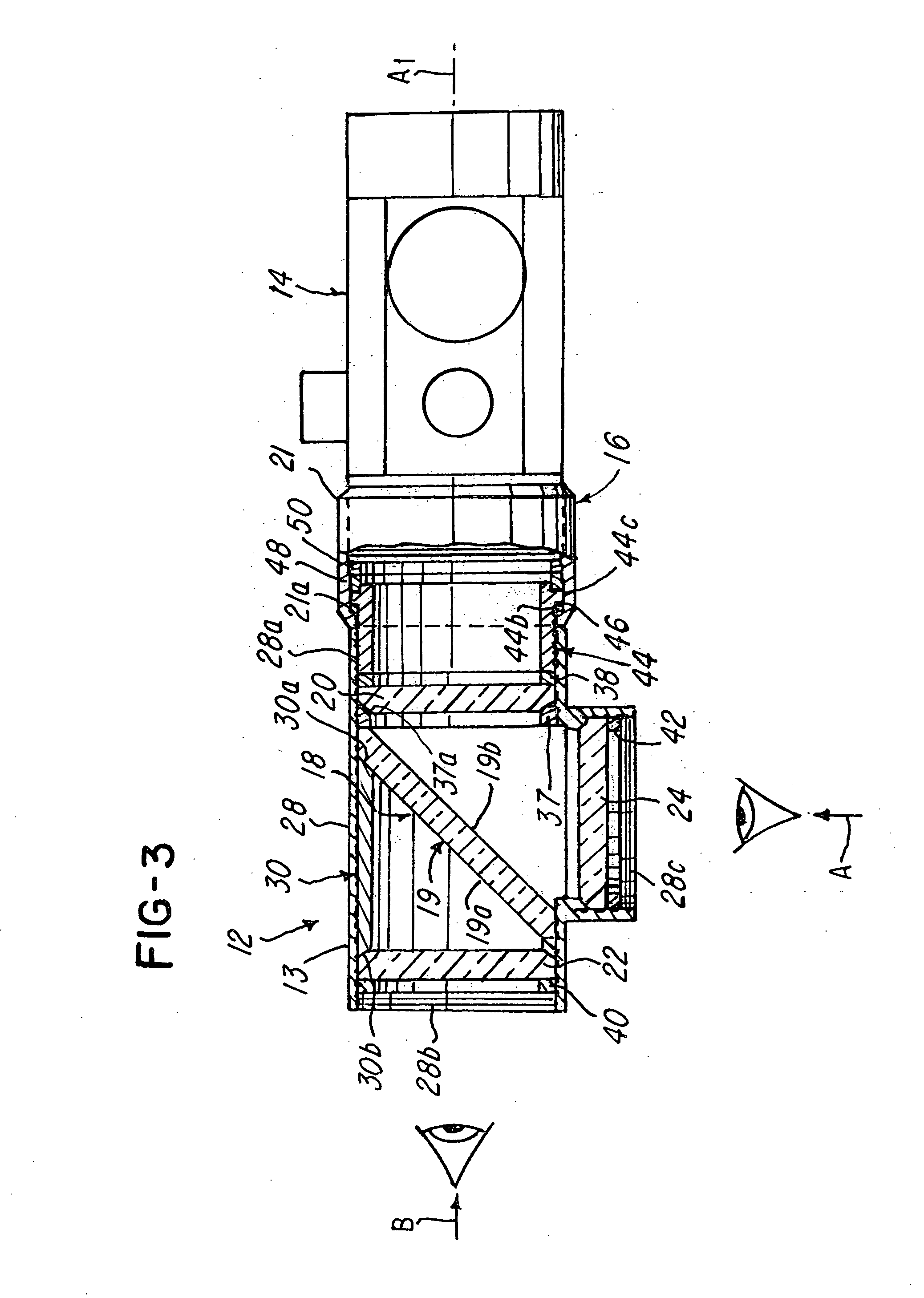
[0007] This invention positions an optical beam splitting element, which can be rotated around a centerline of a pointing axis of the weapon. The beamsplitter is sealed in an optical housing containing other optical elements in which part or all of the elements can rotate with the beamsplitter. The beamsplitter splits the incoming optical path, giving the viewer dual sighting capabilities and allowing him to aim from either the rear of the weapon or from an adjustable side position of the weapon. The side aiming position can be adjusted by pivoting or rotating the beamsplitter assembly around a pointing axis of the device so that the user can aim at a variety of side, overhead or underneath positions. In a rifle or gun scope application, the beamsplitter is positioned behind the targeting reticle and therefore, the aim point of impact is not compromised by small misalignments of the rotating beamsplitting element. In addition, when the dual sight is coupled or situated adjacent to a conventional gun sight, any unlimited eye relief inherent in the sight affords greater flexibility in accommodating the position of the gunner's eye relative to the rear and side viewing ports or positions.
[0008] The sight device, when mounted on small caliber weapons, will allow a gunner to scan an objective or target area and engage targets around corners or over obstacles, quickly and accurately. The intended result is that the user of the sight can see the target and its surroundings in a line or aim point such as a red dot or similar reticle, for firing at a target while concealed and protected from return fire. The sight may be provided with a quick release mount that is compatible with standard gun mounting rails and can be interfaced with red dot, holographic and other types of sighting devices.
[0009] It is an object of the invention to provide an improved sighting device that enables viewing a target from rear and side positions.
[0010] Another object is to provide a penta prism beamsplitter that enables viewing a target from multiple positions associated with a weapon.
[0011] Another object of the invention is to provide a sight that enables side and rear views of a target wherein the image of the target is not inverted.
[0013] Another object of the invention is to provide a sight system and method that enables a user to obtain a view of a target from a position other than the rear of the weapon.

Problems solved by technology

Unfortunately, these scopes or gun sights required the user to look through the scope by placing the user's eye at or near the end of the scope and looking through the scope at the target.

Method used


Image

  • Dual sight scope system and method
  • Dual sight scope system and method
  • Dual sight scope system and method

Examples


Embodiment Construction

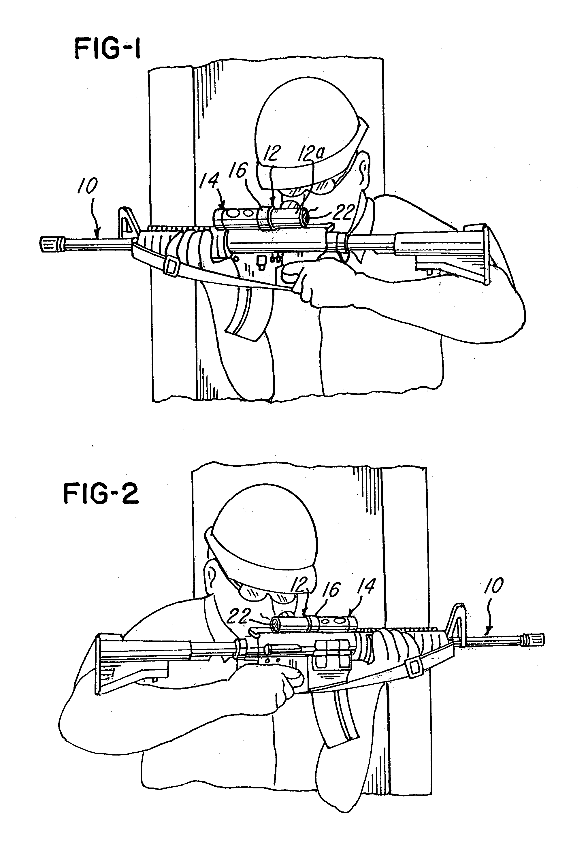
[0045] Referring now to FIGS. 1-6, a first embodiment of the invention is shown. In this embodiment, a weapon 10 is held by a user and has a sight 12 that enables a user to view a target from a plurality of different positions, such as a right side position of the weapon 10 (FIG. 1) or a left side position of the weapon 10 (FIG. 2) or numerous other positions therebetween. The sight 12 has a rear window or port, described later herein, located at an end 12a to enable the user to look through the sight 12 in a traditional rear-view position.

[0046] The sight 12 is mounted on the weapon 16 with a connector 16 (FIGS. 1-3A) adjacent scope 14. It should be understood that the sight 12 may be used either with or without the scope 14. In the embodiment being illustrated, the sight 12 has an axis that is generally coaxial with an axis of the scope 14. The sight 12 comprises a housing 13 that houses an optical element or assembly 18 (FIGS. 3 and 3A). In this embodiment, the optical element o...


PUM


Abstract

A dual sighting optical sight is provided. The sight provides non-inverted images through a rear window and at least one side window so that a user may view a target from either a rear or a side, respectively, of the weapon to which the sight is mounted. The sight is adjustable to a plurality of different positions so that the user can use the sight and weapon from other than directly behind the sight weapon.

Description

CROSS-REFERENCE TO RELATED APPLICATIONS [0001] This application claims the benefit of U.S. provisional application Ser. No. 60 / 543707 filed Feb. 11, 2004, which is incorporated herein by reference and made a part hereof.FEDERALLY SPONSORED RESEARCH [0002] The U.S. Government has a paid-up license in this invention and the right in limited circumstances to require the patent owner to license others on reasonable terms as provided for by the terms of DAAB07-02-C-B302 awarded by the Department of Defense.BACKGROUND OF THE INVENTION [0003] This invention relates to issues associated with urban combat where acquisition and engagement of potential targets often requires close-in viewing and aiming in building interiors. [0004] In the past, a weapon, such as a rifle, may have a scope that enables a user to scan an objective area or target area and engage targets while viewing the target through the scope. Unfortunately, these scopes or gun sights required the user to look through the scope...

Claims


Application Information

Patent Timeline
IPC IPC(8): F41G1/00F41G1/387F41G1/40F41G3/00F41G11/00G02B23/04G02B27/02
CPCF41G1/387G02B23/04F41G11/003F41G1/40
Inventor KARCHER, PHILIP B.HUNT, JOHN D.HOLDER, MARK R.
Owner BAE SYST ELECTRONICS SUSTAINMENT
Learn More