Communication apparatus

Inactive Publication Date: 2005-10-27
NTT DOCOMO INC
View PDF7 Cites 25 Cited by
  • Summary
  • Abstract
  • Description
  • Claims
  • Application Information

AI Technical Summary

Benefits of technology

[0030] An object of the present invention is to provide a communication apparatus to eliminate deterioration of receiving quality caused when plural transmission apparatuses send the same transmission signals, and to eliminate decrease of transmission efficiency caused when signal transmission from a transmission apparatus stops.
[0036] According to the present invention, the communication apparatus can detects the start of data transmission by a first communication apparatus in the plural first communication apparatuses so that the guard interval length can be controlled according to the result of the detection. Thus, when another first transmission apparatus starts to send data, the second communication apparatus can receive the data without deteriorating modulation characteristics. In addition, since the guard interval length is controlled by detecting a stop of data transmission by a first communication apparatus, deterioration of transmission efficiency can be prevented. Thus, according to the present invention, deterioration of receiving characteristics and deterioration of transmission efficiency in the second apparatus can be prevented when plural first communication apparatus sends the same transmission signals.

Problems solved by technology

Therefore, interference between the symbols occurs so that receiving quality is degraded.
However, there are following two problems in the conventional technology.
However, there is a case where the signal cannot be correctly demodulated in the receiving apparatus until the guard interval length is changed.
That is, in the conventional method, a process delay occurs until the transmission apparatus gets feedback from the transmission apparatus, resets the guard interval length and sends a signal.
As mentioned above, in the case where plural transmission apparatuses sends the same transmission signal, even though the above mentioned conventional technology is applied, there is a problem in that a symbol sent until the guard interval length is reset is affected by the interference between symbols so that receiving quality deteriorate (shown as “B” in the figure).
Thus, there is a problem in that redundancy increases so that transmission efficiency decreases.
Therefore, when retransmission of the signal from the radio relay apparatus starts, receiving quality of symbols transmitted until the guard interval length is reset largely deteriorates.

Method used


Image

  • Communication apparatus
  • Communication apparatus
  • Communication apparatus

Examples


first embodiment

[0069] A radio transmission system of the first embodiment of the present invention is configured as shown in FIG. 8, for example. As shown in the figure, the radio transmission system includes plural transmission apparatuses (transmission apparatus 1, transmission apparatus 2) and a receiving apparatus 3. In the radio transmission system of this embodiment, OFDM (Orthogonal Frequency Division Multiplexing) that is one of multi-carrier methods is used for signal transmission. From the transmission apparatus 1 and the transmission apparatus 2, the same transmission signals (OFDM signal) are sent to the receiving apparatus 3. In this embodiment, each of the transmission apparatuses 1 and 2 and the receiving apparatus 3 corresponds to a communication apparatus connected to a predetermined line for sending and receiving data.

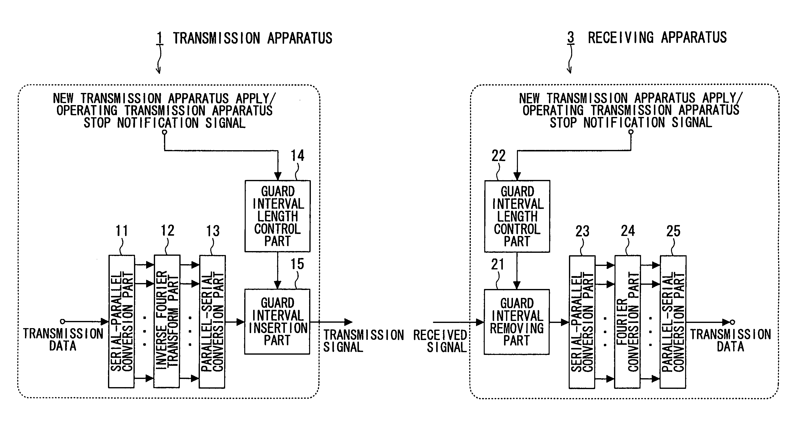
[0070]FIG. 9 is a block diagram showing configurations of the transmission apparatus and the receiving apparatus. Since the transmission apparatus 1 and the transm...

second embodiment

[0103] In the following, the second embodiment is described in which plural transmission apparatuses (to be refereed to as base stations hereinafter) send the same transmission signals to a receiving apparatus (to be refereed to as mobile station hereinafter). In this embodiment, the present invention is applied to handover in cellular mobile communications shown in FIG. 4.

[0104] In an handover region on an border of cells, the same transmission signals are sent to a mobile station form plural base stations. However, since distances between each base station and the mobile station are different, even if the base stations send signals at the same time, the mobile station receives the signals at different times.

[0105] In addition, when the base stations are not precisely synchronized with each other, the base stations send signals at different times so that the mobile station receives the signals from the base stations at different times. In such a case, if a difference between dela...

third embodiment

[0106] In the second embodiment, an embodiment is described in which the present invention is applied to handover in mobile communications in a cellular system. On the other hand, the present embodiment is an embodiment in which the present invention is applied to a radio relay system in which a radio relay apparatus relays a transmission signal from a transmission apparatus to a receiving apparatus. The radio relay system of this embodiment is similarly configured to the radio relay system shown in FIG. 5 described as prior art. Therefore, reference numbers 310, 320 and 330 in FIG. 5 are assigned to the transmission apparatus, the radio relay apparatus and the receiving apparatus respectively in this embodiment. In addition, the transmission apparatus and the receiving apparatus of this embodiment are similarly configured to those of the first embodiment.

[0107]FIG. 17 is a block diagram showing a configuration of the radio relay apparatus of the present embodiment.

[0108] As shown...


PUM


Abstract

A communication apparatus in a radio transmission system in which plural first communication apparatuses sends the same transmission signals and a second communication apparatus receives the transmission signals is disclosed. The communication apparatus functions as one of the plural first communication apparatuses, and the communication apparatus includes: a detection part for detecting a start or a stop of data transmission performed by a first communication apparatus that is different from the communication apparatus; and a guard interval length control part for controlling a guard interval length on the basis of a detection result of the detection part.

Description

BACKGROUND OF THE INVENTION [0001] 1. Field of the Invention [0002] The present invention relates to a communication apparatus in a radio transmission system in which plural communication apparatuses sends the same OFDM signals to a receiving apparatus. [0003] 2. Description of the Related Art [0004] In mobile communications, the OFDM (Orthogonal Frequency Division Multiplexing) transmission method is being studied as a technology for decreasing characteristics deterioration due to effects of delay waves. Since the OFDM transmission method uses multiple sub-carriers to transmit data, a symbol length of each sub-carrier can be set long, so that characteristics deterioration due to effects of delay waves can be decreased. [0005] In addition, by using a guard interval that is copied data of a part of an OFDM modulated signal and that is added to the data symbol, the characteristics deterioration due to effects of delay can be further decreased. [0006]FIG. 1 is a block diagram of a conv...

Claims


Application Information

Patent Timeline
IPC IPC(8): H04J11/00H04B7/26H04L27/26H04W16/24H04W16/26H04W72/04H04W88/02
CPCH04L27/2605H04L27/2602H04L27/26025
Inventor ASAI, TAKAHIROFUJII, HIROMASATANAKA, TETSUSUDA, HIROHITO
Owner NTT DOCOMO INC
Why Eureka
Try Eureka