Liquid crystal display method and liquid crystal display device improving motion picture display grade
a liquid crystal display and liquid crystal technology, applied in the direction of instruments, television systems, signal generators with optical-mechanical scanning, etc., can solve the problems of complex circuitry, display grade deterioration, and afterimages that may be seen in motion picture display
- Summary
- Abstract
- Description
- Claims
- Application Information
AI Technical Summary
Benefits of technology
Problems solved by technology
Method used
Image
Examples
first embodiment
(First Embodiment)
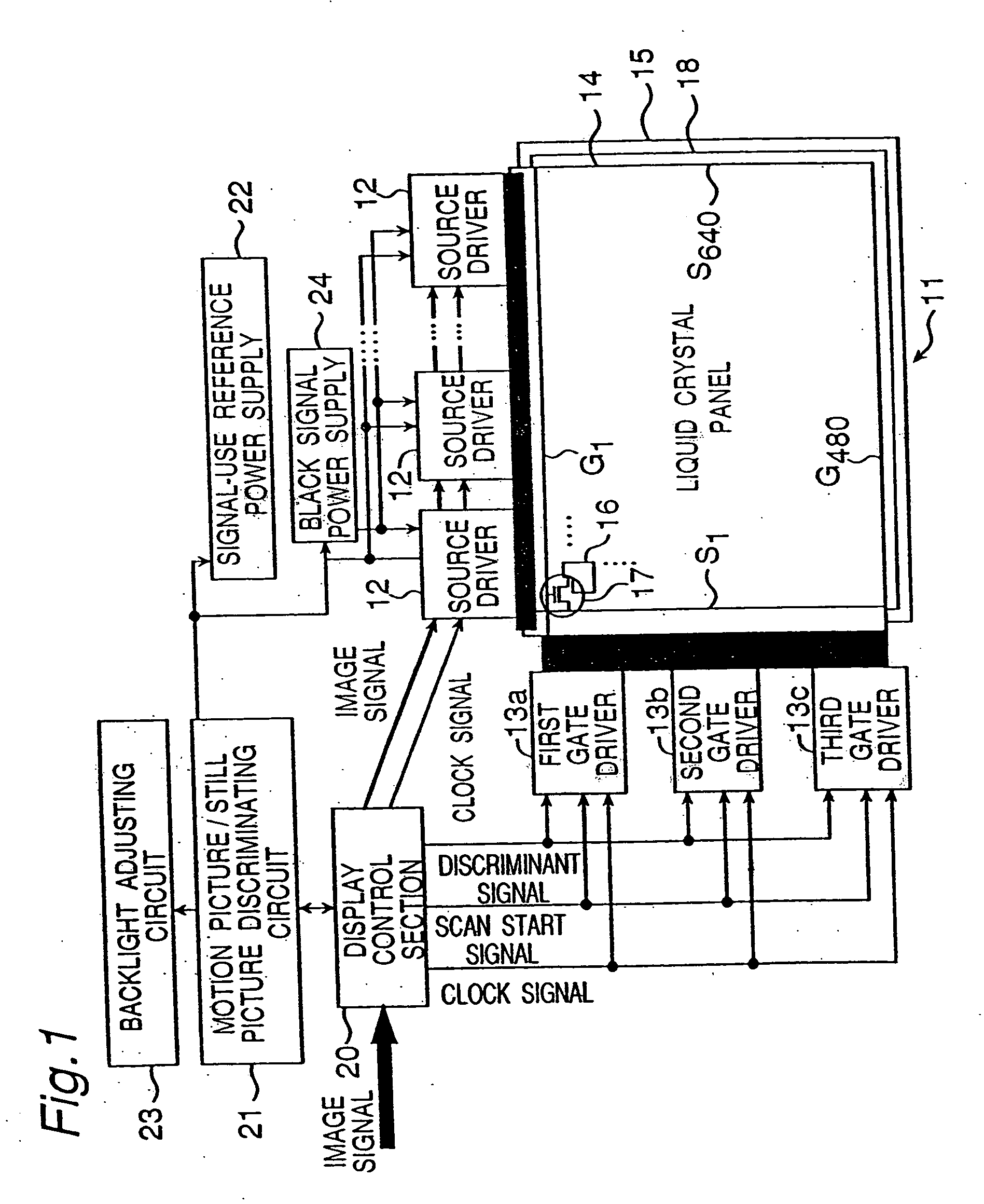
[0137]FIG. 1 is a schematic block diagram of an active matrix type LCD device as an LCD device of this embodiment. The LCD device of this embodiment has a liquid crystal panel 11, a plurality of source drivers 12 and a plurality of gate drivers 13. The liquid crystal panel 11 has a TFT substrate 14 and a counter substrate 15. On the TFT substrate 14, are formed pixel electrodes 16 arrayed in a matrix shape, TFTs 17 the drains of which are connected to the pixel electrodes 16, gate lines G connected commonly to gates of the TFTs 17 of each row and arrayed in parallel, and source lines S connected commonly to sources of the TFTs 17 of each column and arrayed in parallel. On the counter substrate 15 opposed to the TFT substrate 14 with a specified spacing, counter electrodes 18 are formed opposite to the pixel electrodes 16. Also, although not shown, liquid crystals are sandwiched between the pixel electrodes 16 and the counter electrodes 18.
[0138] The liquid crystal...
second embodiment
(Second Embodiment)
[0187] The LCD device in this embodiment is similar in general configuration to the active matrix type LCD device of the first embodiment shown in FIG. 1. However, the LCD device in this embodiment employs the S-XGA (super XGA) panel for the liquid crystal display section. The pixels count 1280 (tripled for color display)×1024, differing from the VGA panel of the first embodiment by about a double in terms of the number of gate lines G. Therefore, as in the first embodiment, if the data signal and the reset signal are alternately outputted with the same output time width, the selection time for one horizontal line is about 16.7 ms (one frame period) / 1024 (lines) / 2≈about 8.1 μs. Thus, enough signal write to the pixels (i.e., charging) cannot be achieved.
[0188] In addition, from the viewpoint of the power of the TFT devices that switch the connection between the particular electrodes and the source lines S, the selection time for one horizontal line is necessarily ...
third embodiment
(Third Embodiment)
[0203] The LCD device of the first embodiment, when used under low temperatures, become lower in the response speed of liquid crystals, so that the data signal for the succeeding frame is written before the black display by the reset signal is completed. As a result, there is a problem that the amount of blurs of motion pictures is increased. Whereas this problem can be solved by applying the second embodiment, i.e., by switching the discriminant signal from the display control section 20, the problem can also be solved by controlling the response time which elapses while the transmissivity changes from one corresponding to the data signal to another corresponding to black, so that the response time falls within the frame period. Below described is a method for controlling the response time that elapses while the transmissivity changes from an arbitrary one corresponding to the data signal to another corresponding to black.
[0204] The following response time contro...
PUM
| Property | Measurement | Unit |
|---|---|---|
| time | aaaaa | aaaaa |
| time | aaaaa | aaaaa |
| time | aaaaa | aaaaa |
Abstract
Description
Claims
Application Information
 - R&D
- Intellectual Property
- Life Sciences
- Materials
- Tech Scout
- Unparalleled Data Quality
- Higher Quality Content
- 60% Fewer Hallucinations
Browse by: Latest US Patents, China's latest patents, Technical Efficacy Thesaurus, Application Domain, Technology Topic, Popular Technical Reports.
© 2025 PatSnap. All rights reserved.Legal|Privacy policy|Modern Slavery Act Transparency Statement|Sitemap|About US| Contact US: help@patsnap.com


