
Filter using multilayer ceramic technology and structure thereof

Active Publication Date: 2005-10-27
CHANG SHENG FUH +1
View PDF6 Cites 36 Cited by
  • Summary
  • Abstract
  • Description
  • Claims
  • Application Information

AI Technical Summary

Benefits of technology

[0012] It is an object of the present invention to provide a filter circuit. Comparing to the planar filter, the filter has the advantages of smaller size, higher transition slope at upper and lower passband edges, the higher selectivity of two adjacent channels, greater suppression of the higher order hormonics, and lower insertion loss than that of other filter.
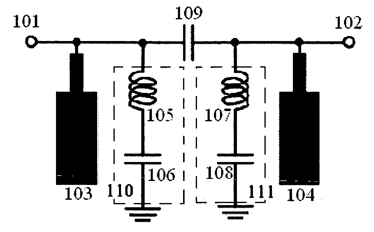
[0015] According to one aspect of filter circuit of the present invention, a first transmission zero is generated when the first lumped resonator resonates naturally, a second transmission zero is generated when the second lumped resonator resonates naturally, a third transmission zero is generated when the first step-impedance resonator resonates naturally and a fourth transmission zero is generated when the second step-impedance resonator resonates naturally. The generation of the transmission zeros can have higher slope at upper and lower passband edge to obtain the high selectivity between two adjacent channels. The frequency of the transmission zeros can be controlled by varying the value of the capacitance. Another, the parasitic ground capacitance of the coupling capacitor can be absorbed by the first step-impedance resonator and the second step-impedance resonator, and therefore the practical length of the first step-impedance resonator and the second step-impedance resonator are shorter than the quarter wavelength of the operating frequency.
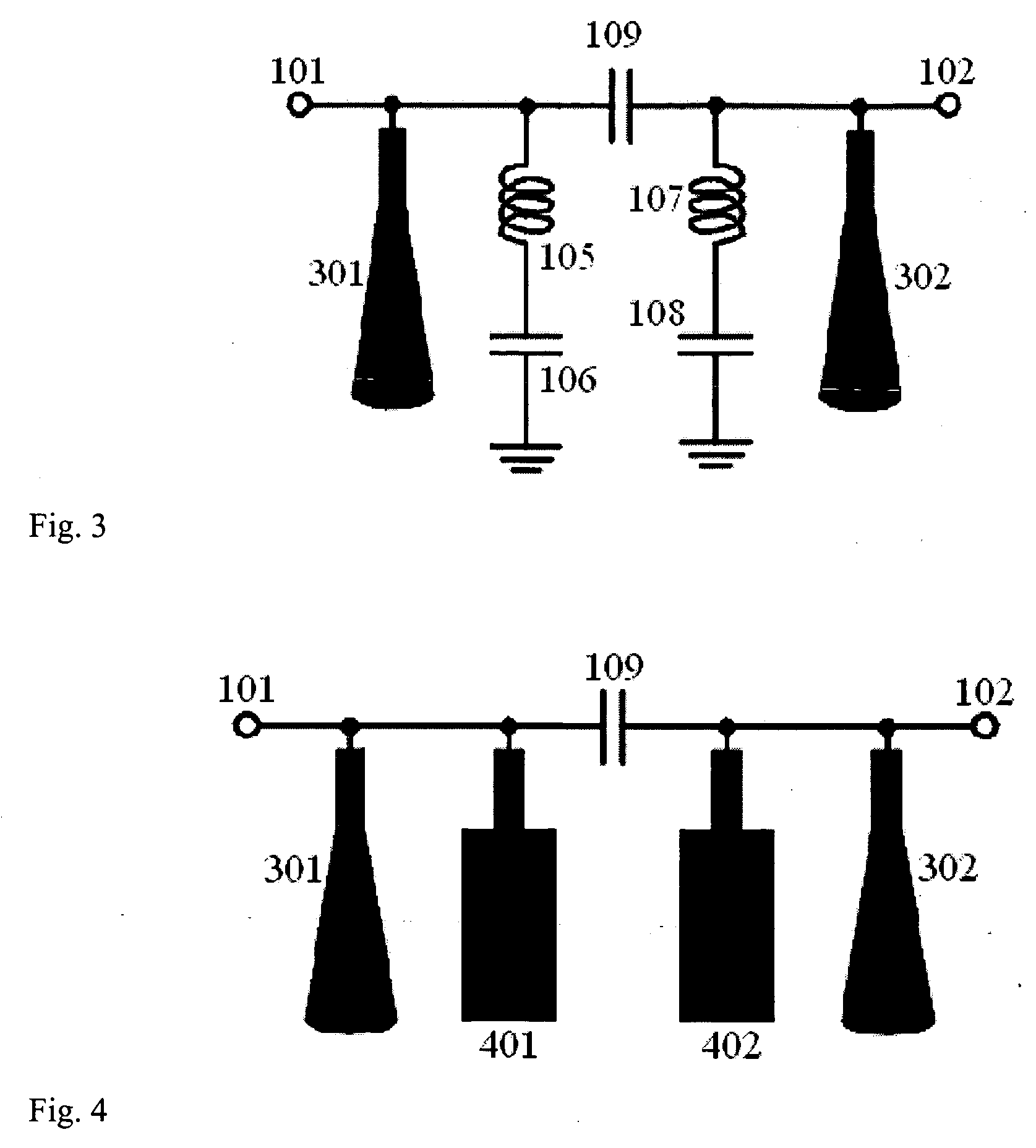
[0018] According to one aspect of filter structure using multi-layer ceramic technology of the present invention, the input electrode and the output electrode can be coplanar feed-in or non-coplanar feed-in. This input and output feed-in design can conform the measuring technology and brings more flexibility.
[0019] According to another aspect of filter structure using multi-layer ceramic technology of the present invention, the third metal piece on the inductance layer and the fifth metal piece on the capacitance layer are in natural series-resonance to provide a first transmission zero and the fourth metal piece on the inductance layer and the sixth metal piece on the capacitance layer are in natural series-resonance to provide a second transmission zero. The generation of the transmission zeros can provide higher slope at upper and lower passband edge. The related position and size of the metal pieces can determine the coupling amount, and further determine the frequencies of transmission zeros.
[0021] According to another aspect of filter structure using multi-layer ceramic technology of the present invention, the parasitic ground capacitance of the first coupling capacitance layer and the second coupling capacitance layer can be absorbed by the seventh metal piece and the eighth metal piece on the step-impedance layer, and therefore the practical length of the seventh metal piece and the eighth metal piece are shorter than one quarter wavelength of the operating frequency. Such design makes the whole volume more compact to conform the light, thin, short, small trend of the communication system.

Problems solved by technology

The distributed circuit operated at lower frequencies will have higher sizes, and therefore the semi-lumped or distributed filter is not suitable as operating below 200 MHz due to size limitation.
Although the lumped filter has feature of the compact size, it become impractical as operating at frequencies higher than GHz due to larger power dissipation and the parasitic effect.
The lumped circuits can be much improved by the use of the superconductor recently, but such application is limited except in the universal space since the superconductor device must operate at ultra low temperature.
Such filters use the transmission line of quarter wavelength to realize the impedance transformer, addimitance transformer and resonator, and therefore the use of low dielectric constant materials are not suitable as operating between several hundred MHz and several GHz.
However, there are two disadvantages in the patent.
The second is that the filter is not easily integrated with other sub-module into single and miniaturized module of multi-function since the filter can not be embedded into the dielectric layer.
However, such filter needs larger grounding capacitance, and therefore the use of the high dielectric constant substrate is needed to reduce the size.
This shift may be compensated by post-tuning process put it increases the cost of the filter.

Method used


Image

  • Filter using multilayer ceramic technology and structure thereof
  • Filter using multilayer ceramic technology and structure thereof
  • Filter using multilayer ceramic technology and structure thereof

Examples


Embodiment Construction

[0034] Although the invention has been explained in relation to several preferred embodiments, the accompanying drawings and the following detailed description are the preferred embodiment of the present invention. It is to be understood that the following disclosed descriptions will be examples of present invention, and will not limit the present invention into the drawings and the special embodiment.

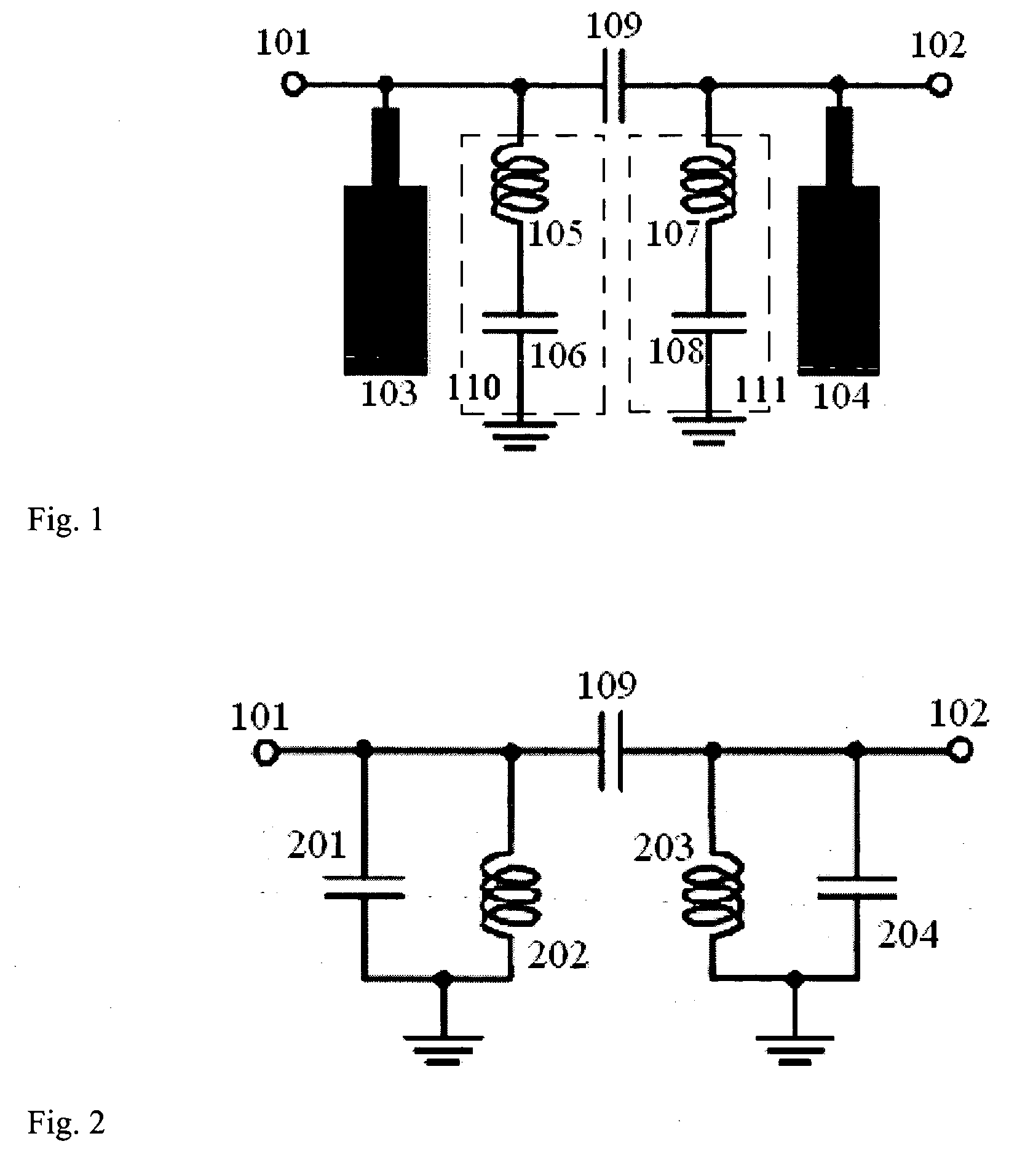
[0035]FIG. 1 is a circuit diagram illustrating the first embodiment of the filter according to the present invention. The filter circuit mainly comprises an input port 101, an output port. 102, lumped resonators 110□111, step-impedance resonators 103□104 and a coupling capacitor 109. The step-impedance resonator 103 is electrically connected to the input port 101, and the step-impedance resonator 104 is electrically connected to the output port 102. The coupling capacitor 109 is used for the coupling of the first lumped resonator 110 and the first step-impedance resonator 103 to the s...


PUM


Abstract

The present invention discloses a filter using multilayer ceramic technology. The filter comprises an input port, an output port, a first lumped resonator and a first step-impedance resonator connected to the input port, a second lumped resonator and a second step-impedance resonator connected to the output port, a coupling capacitor used for the coupling of the first lumped resonator and the first step-impedance resonator to the second lumped resonator and the second step-impedance resonator. The filter according to the present invention can provide the multi-transmission zeros in the stopband to isolate the adjacent channel and suppress the harmonics, and provide the transmission poles in the passband to have lower insertion loss. In addition, a manufacturing method for the filter using multilayer ceramic technology is also disclosed.

Description

BACKGROUND OF THE INVENTION [0001] 1. Field of the Invention [0002] The present invention relates to a structure and design of the communication device, and more particularly, to a structure and design of the filter using multi-layer ceramic technology. [0003] 2. Description of the Related Art [0004] Recently, the quality of communication service is getting higher due to the development of the advance wireless communication technology. Current communication products dainty not only to be light, thin, short and small, but also have good and stable communication quality. Particularly, in the wireless communication receiver, the filter is an indispensable device. The filter is mainly used for receiving the required signal and rejecting the undesired interference and noise attained by the antenna. In general, the filters are divided into lowpass filter, highpass filter, bandpass and bandstop filter according to their spectrum characteristic. Lowpass filter rejects the higher frequency s...

Claims


Application Information

Patent Timeline
IPC IPC(8): H01P1/203H03H7/01
CPCH01P1/20345H03H7/1775H03H7/1758H03H7/0123H03H2001/0085
Inventor CHANG, SHENG-FUHJENG, YNG-HUEY
Owner CHANG SHENG FUH
Learn More