
Method and apparatus for treating skin

Inactive Publication Date: 2005-10-20
EVA MATILDA BOWN
View PDF10 Cites 27 Cited by
  • Summary
  • Abstract
  • Description
  • Claims
  • Application Information

AI Technical Summary

Benefits of technology

[0017] The apparatus of the invention may be provided in two different forms, one suited to use by a medical practitioner in a clinic or surgery (where autoclaving is routine) and the other more adapted for use in beauty salons, where autoclaving is not generally available and operator expertise is less. The salon procedure will generally be used to remove liver spots and hormonal discoloration, which are superficial. Since the practitioner in the salon may not be as skilled as a doctor and lighting and other conditions may not match those of a surgery, the salon version will normally employ guards that limit depth of cut and minimize debris spread, even if the point of contact between the burr and the skin is thereby obscured. The use of disinfectant wipes to clean the body in the salon version will generally be satisfac

Problems solved by technology

The reasons seem to be, first, that these methods are generally not safe for the patient or client because they can easily result in the removal of too much skin and, second, that they are not safe for the practitioner because they tend to spray skin tissue about.
A small arcuate shield covers a small portion of the brush to somewhat reduce tissue spray, but significant tissue spray will still occur and there is serious danger of removing too much skin, particularly if the color or texture of the skin is changed by the refrigerant.
While motor-driven sanding drums used for podiatry [eg, that disclosed in French patent 2,728,777] also spread skin debris widely, the debris is likely to be dry (as already noted).
U.S. Pat. No. 6,391,034 discloses a surgical device for removing unwanted scar tissue from large burned areas, which is unsuitable for cosmetic purposes and employs a rotor comprising a wire brush, grinding cylinder or

Method used


Image

  • Method and apparatus for treating skin
  • Method and apparatus for treating skin
  • Method and apparatus for treating skin

Examples


Example

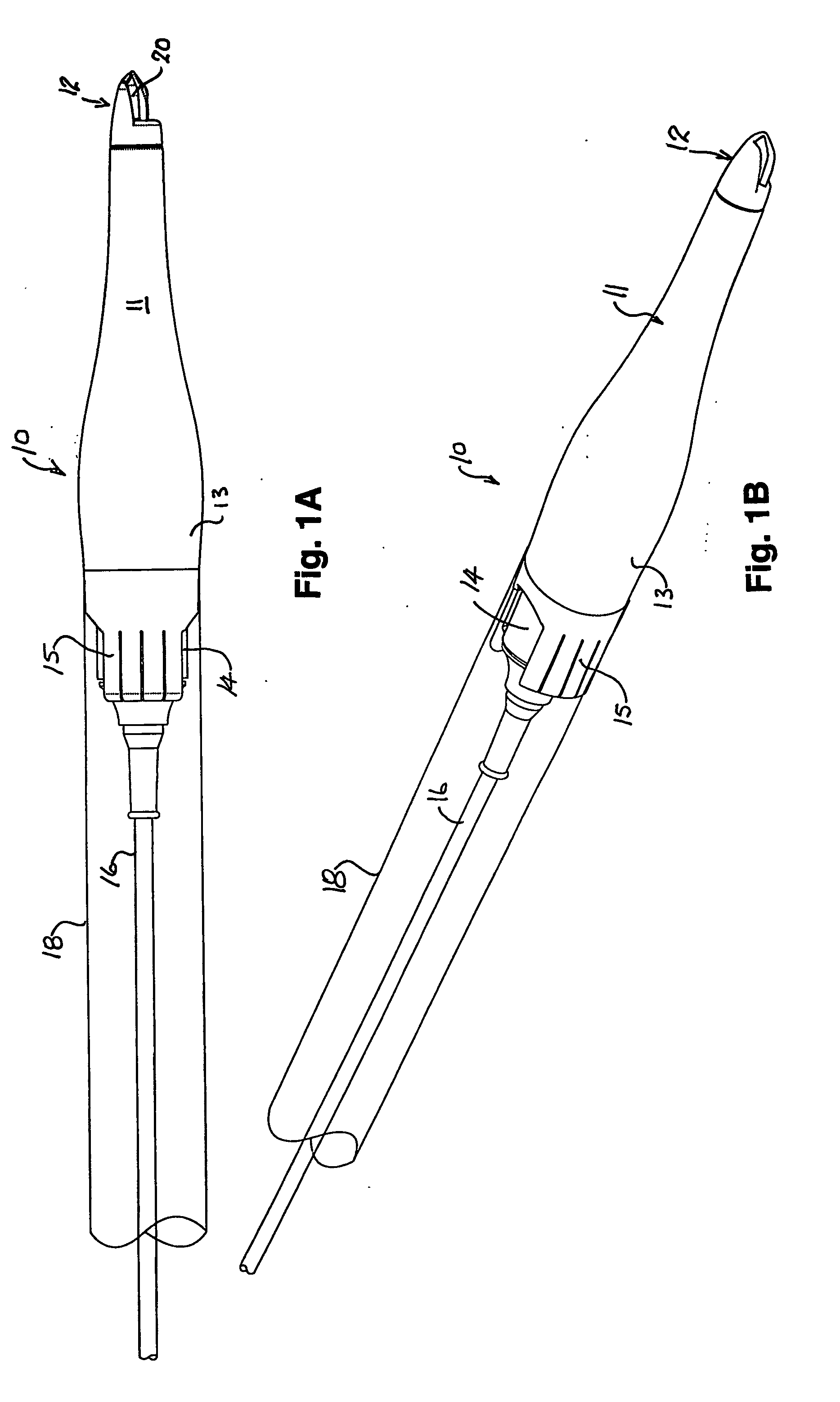
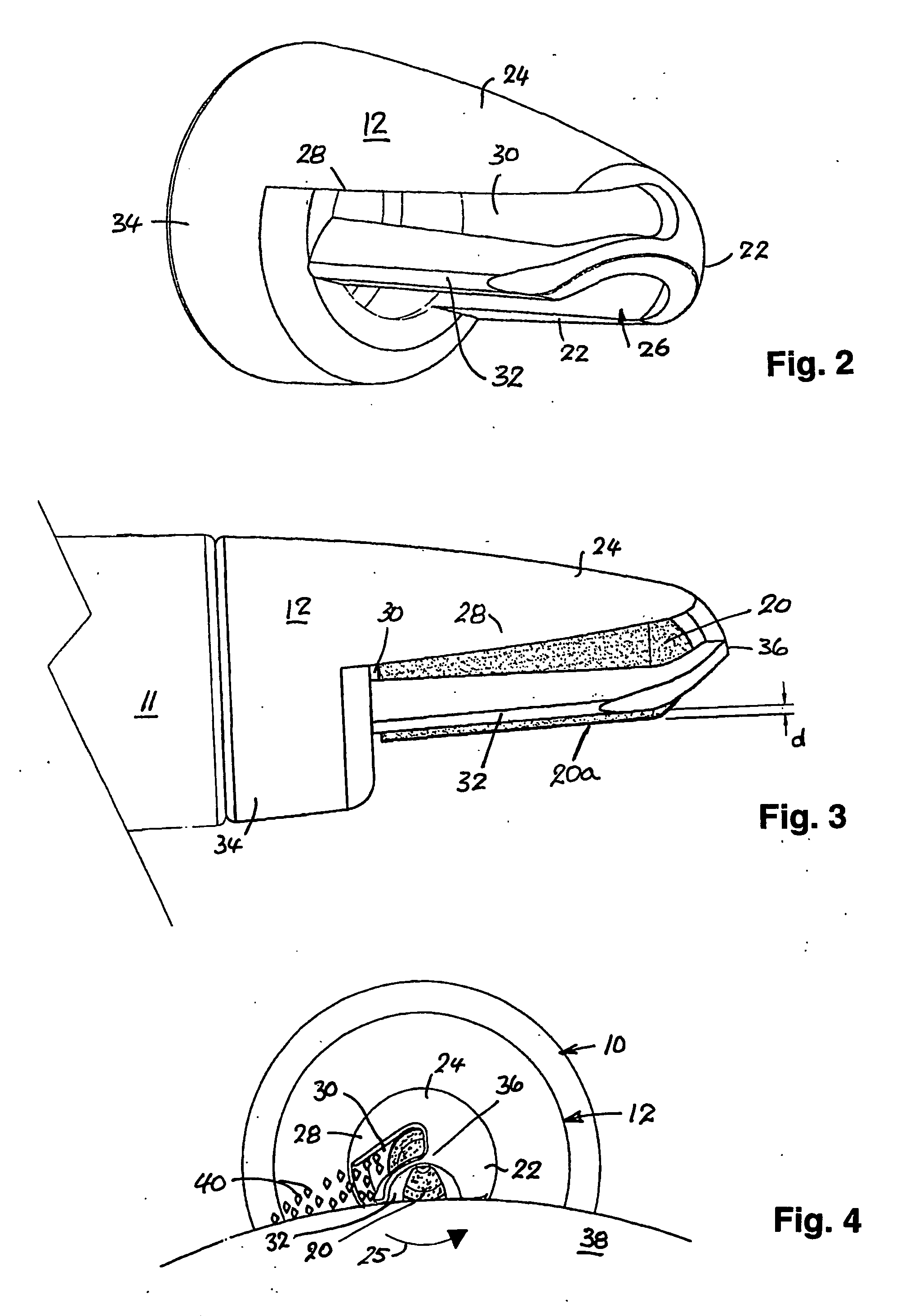
[0032]FIGS. 1A and 1B are two views of the device 10 of the first example, which comprises a driver assembly or hand-piece 11 fitted with a disposable shield 12 on its distal end, driver assembly 11 having a hollow tubular body 13 into the proximal end of which a high-speed low-voltage motor 14 and shaft (not shown) are inserted and held by clips 15, the power lead for motor 14 being shown at 16. In this example, a thin transparent tubular sheath 18 is fitted over clips 15 and the proximal end of driver assembly 11 to keep motor 14 and near portion of lead 16 clean. A burr 20, just visible in FIG. 1A, is fitted on to the end of the motor shaft (not shown) and is largely covered by shield 12.

[0033] We have found molded tubular abrasive paper or fabric burrs having a relatively coarse grit size—between 120 and 350—a diameter of a few millimeters and rotated at about 10,000 rpm are suitable. Abrasive elements of this nature are commercially available are formed from paper or fabric ba...


PUM


Abstract

Methods and apparatus for removing skin blemishes and wrinkles by abrasion using a burr are disclosed. In one example a hand-held device (10) is used. It has a body (11) into the proximal end of which a low-voltage motor (14) is removably clipped and onto the distal end of which a shield or fitment (12) is removably attached. A rotary burr (20) is located within the shield so as to be rotatably coupled to the motor shaft. Preferably, the burr (20) and the shield (12) are attachable and removable as a single-use disposable fitment. The shield (12) may be located off-center with respect to the burr (20) so that rotation of the shield with respect to the body (11) will to expose more or less of the burr. A slot (32) may be formed in the wall of the shield (12) to discharge skin debris onto the skin being treated where it can be wiped away.

Description

TECHNICAL FIELD [0001] This invention relates to methods and apparatus for removing skin blemishes, wrinkles and the like using a rotating abrasive burr. [0002] The methods and devices of the invention are suitable for the reduction or removal of small brown skin blotches—sometimes called ‘liver spots’ or ‘age patches’—that appear on the face, chest and the backs of hands and, while related to sun exposure, are not freckles. The methods and devices are also suited to the reduction or removal of larger patches of brown skin discoloration, which appear on the faces and necks of women during pregnancy or soon after. In addition, the methods and devices of the invention are applicable to the reduction or removal of facial wrinkles and lines, particularly, though not exclusively, those in the perioral and periorbital areas. While the ‘depth of cut’ needed to remove liver spots is such that, with care, the procedure can be performed in a beauty salon, that required to remove most wrinkles...

Claims


Application Information

Patent Timeline
IPC IPC(8): A61B17/00A61B17/32A61B17/54
CPCA61B17/54A61B2017/320004A61B2017/00747
Inventor BROWN, EVA MATILDAMOBBS, WILLIAM L.
Owner EVA MATILDA BOWN
Learn More