
Obtaining channel quality information in a wireless communication network

a wireless communication network and channel quality technology, applied in the field of wireless cdma, can solve the problems of fading can be a problem for transmission of mobile data, the receiver will progressively enter the zone of constructive and destructive interference, and the combination can be either constructive or destructiv

Active Publication Date: 2005-10-20
SONY CORP
View PDF11 Cites 162 Cited by
  • Summary
  • Abstract
  • Description
  • Claims
  • Application Information

AI Technical Summary

Problems solved by technology

The combination can be either constructive or destructive.
When either the receiver moves or the surroundings of the receiver move, the receiver will progressively enter zones of constructive and destructive interference.
This fading can be a problem for transmission of mobile data.
This strategy is wasteful of transmit power.
The disadvantage with this system is that these dedicated channels need to be maintained: these dedicated channels consume scarce power and code resources.
The disadvantage is that channel quality information is received by the scheduler in the Node B only infrequently.
However, a streaming traffic model is not ideally suited to exploitation of multi-user diversity (since a minimum “drip-feed” of allocation is required in order to maintain the stream).
This channel quality request message may be small and thus have an insignificant impact on overall system throughput.
However, these methods of requesting channel quality information require amendments to the 3GPP standards and do not propose how these channel quality information requests would be scheduled by the Node B or how the UE would derive the channel quality information that is to be returned to the UE.

Method used


Image

  • Obtaining channel quality information in a wireless communication network
  • Obtaining channel quality information in a wireless communication network
  • Obtaining channel quality information in a wireless communication network

Examples


embodiments

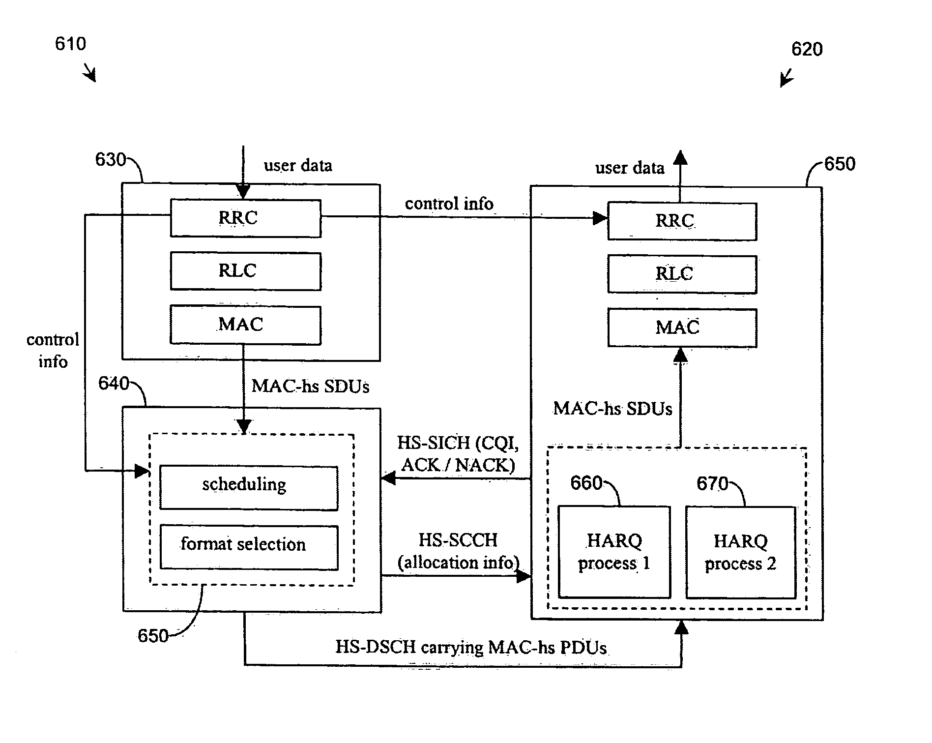
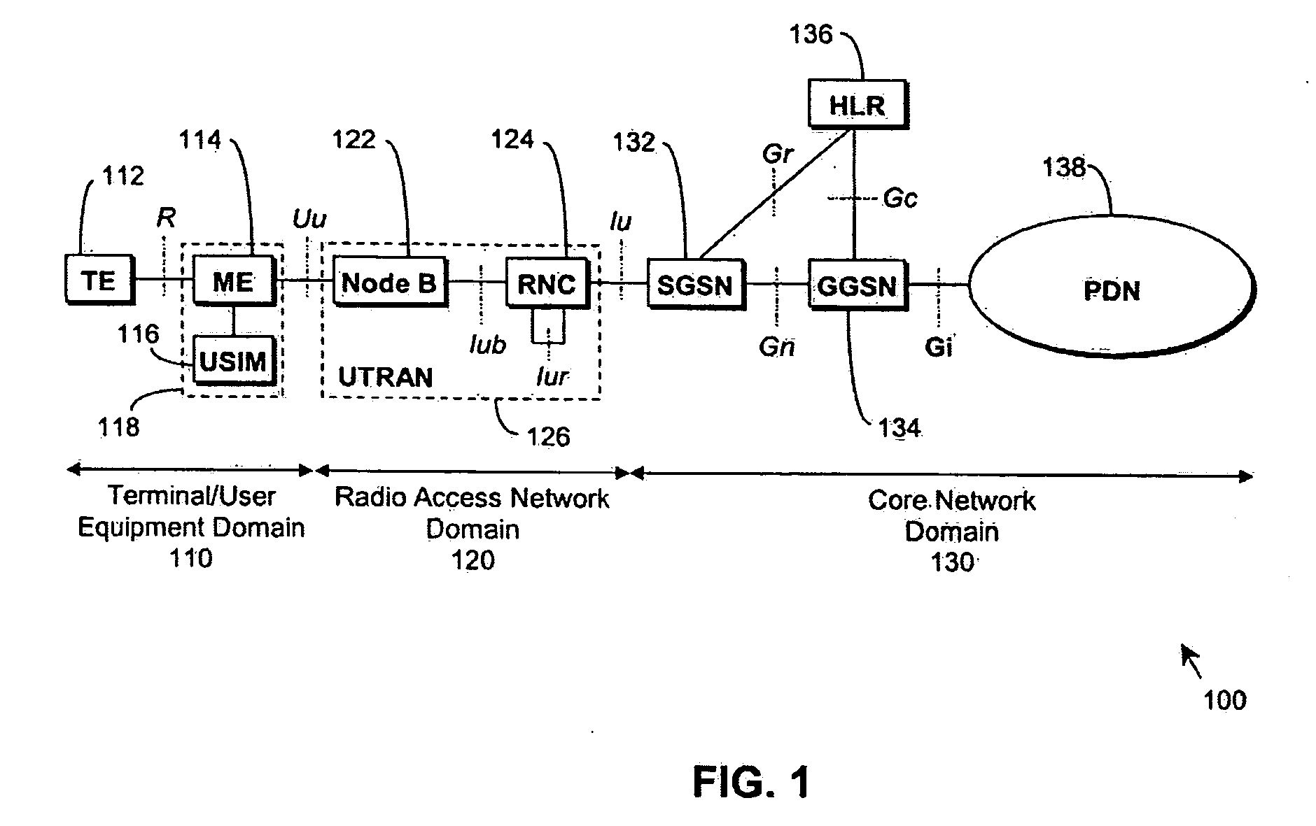
[0090] In practice an embodiment of the invention may be based on a 3G (3rd Generation) TDD Node B. This Node B forms part of a 3G cellular network and services multiple UEs. The Node B transmits and receives signals from one or several antennas to which it is attached. The Node B is positioned at a cell site.

[0091] The Node B implements the TDD HSDPA feature as specified by 3GPP. The Node B schedules UEs in priority order according to a proportional fair scheduling algorithm. The proportional fair scheduling metric is a function of the amount of data pending for transmission to that UE, a list of times that the UE has been scheduled at previously and the channel quality at the UE.

[0092] The Node B gains channel quality information on the HSSICH channel. Channel quality information is thus returned to the Node B either as a consequence of allocation of user-data bearing HS-DSCH resources or as a consequence of the Node B sending a CQI request to the UE.

[0093] The Node B partition...


PUM


Abstract

Obtaining channel quality information in a wireless communication network is described. A base station allocates a resource to remote stations in order to receive channel quality information back from remote stations. The resource allocated to a remote station contains no higher layer data. A scheduler in the base station uses the channel quality information in order to schedule remote stations and / or to decide on the channel coding and / or modulation to be applied to the data transmission. A mechanism is provided to ensure that data transmitted on HS-DSCH is not transmitted to higher layers. This may provide a convenient method of obtaining channel quality information allowing for improved scheduling and thus improved performance of the communication system.

Description

CROSS-REFERENCE TO RELATED APPLICATIONS [0001] This application claims the benefit of United Kingdom patent application number 0319567.4, filed Aug. 20, 2003, which is incorporated by reference in its entirety herein. FIELD OF THE INVENTION [0002] This invention relates to code division multiple access (CDMA) systems, and particularly (though not exclusively) to wireless CDMA systems such as 3rd Generation Partnership Project (3GPP) systems utilising packet data services and employing High Speed Downlink Packet Access (HSDPA). BACKGROUND OF THE INVENTION [0003] There has been a growth in demand for packet switched wireless data services due to the growth in internet applications. A typical channel over which these data services are delivered is a radio channel. There are available radio channels in an increasing number of frequency bands. A frequency band of particular interest is the IMT-2000 frequency band (at a frequency of about 2 GHz). This frequency band is used for delivery o...

Claims


Application Information

Patent Timeline
IPC IPC(8): H04J13/00H04L12/56H04W24/06H04W72/08H04W72/12H04W92/10
CPCH04W24/06H04W92/10H04W72/0413H04W72/21H04L1/0003H04L1/1812H04W88/08H04W72/231H04W72/1273H04W24/08H04W72/542H04L1/0026
Inventor BEALE, MARTIN WARWICK
Owner SONY CORP
Learn More