
Mechanical pipe joint, gasket, and method for restraining pipe spigots in mechanical pipe joint bell sockets

a technology of mechanical pipe joints and bell sockets, which is applied in the direction of hose connections, mechanical apparatus, sleeve/socket joints, etc., can solve the problems of less space within the bell socket for the elastomeric gasket, the spigot is exposed, and the underlying gasket construction costs are added to the construction cost of materials and labor, so as to achieve uniform radial locking and light weigh

Active Publication Date: 2005-10-20
US PIPE & FOUNDRY
View PDF47 Cites 30 Cited by
  • Summary
  • Abstract
  • Description
  • Claims
  • Application Information

AI Technical Summary

Benefits of technology

[0012] The present invention provides an improved restraining gasket for use in a mechanical pipe joint that improves sealing and restraint functions in joints between fluid piping members. Specifically, the invention provides an improved sealing area between an inner surface of a bell socket and an outer surface of a pipe spigot. The gasket of the present invention also provides a more evenly-distributed radial restraining force on an improved outer surface area of a pipe spigot. The present invention also provides for a mechanical pipe joint utilizing the gasket, and a method for restraining a pipe spigot within a bell socket, utilizing the gasket.
[0014] The restraining gasket of the present invention is designed to axially separate the sealing and locking functions of the gasket and achieve, for example, the following advantages: (1) an increase in sealing area within the bell socket, (2) an increase in restraining area in contact with the pipe spigot, as the arcuate locking members are formed in long arcuate sections to conform to the cross-section of the pipe spigot outside the bell socket, and (3) an improved construction of the restraining gasket, so that no separate locking and sealing parts are required.
[0015] The restraining gasket of the present invention may be used in the mechanical pipe joint and method of sealing and axially securing a male piping member within an adjoining bell socket of the present invention. The mechanical pipe joint includes a lighter-weight gland having a recessed bearing surface that contacts the outer surfaces of the arcuate locking members. Since the gland has a recessed bearing surface, it contains less material than a standard mechanical joint gland, making it lighter and more easily manipulated by the technician assembling the joint. In the mechanical pipe joint of the present invention, the rigid arcuate locking members may be located outside of the bell socket so that the gland bearing surface may transmit the axial attachment force of the gland bearing surface to the axially-adjacent sealing portion of the gasket. Furthermore, the gland bearing surface may transmit a portion of the axial attachment force into the radial direction so as to urge the locking members into contact with the outer surface of the pipe spigot as the gland is axially attached to the bell socket.
[0016] The bell socket of the present invention includes a sealing cavity, which is filled by the sealing portion of the gasket so that the sealing portion of the gasket resides completely within the bell socket, axially separated from the restraining portion of the gasket. This bell socket and gasket arrangement ensures that the circumferential sealing contact between the sealing portion, bell socket, and the pipe spigot, is uninterrupted around the entire circumference of the pipe joint. This feature improves the sealing surface area of the gasket.
[0018] The gasket, mechanical pipe joint, and method of the present invention provide a more complete circumferential seal between the pipe spigot and the inner surface of the bell socket as well as a more evenly distributed radial locking force between the inner surfaces of the arcuate locking members and the outer surface of the pipe spigot. These advantages are provided in a restraining gasket that is configured for use with an improved method and mechanical pipe joint utilizing a lighter weight gland and a bell socket that provides a sealing cavity designed to receive the sealing portion of the gasket. Additionally, the present invention provides a more effective distribution of the axial attachment force imparted on the arcuate locking members by the bearing surface of the gland so that the sealing portion of the gasket is fully compressed and seated within the sealing cavity of the bell socket before the arcuate locking members are urged into radial contact with the outer surface of the pipe spigot.

Problems solved by technology

While the skid pads in the Richardson '513 Patent prevent premature engagement of the locking ring with the outer surface of the spigot, they add cost of materials and labor to the construction of the underlying gasket.
As a result, less space is available within the bell socket for the elastomeric gasket.
In this case, however, conventional hardened steel locking segments having a relatively short length can expose the PVC pipe spigot to large localized forces that might damage the PVC material.
The extra material added to the gland in the “forward end” structure adds weight and manufacturing complexity to the gland structure.

Method used


Image

  • Mechanical pipe joint, gasket, and method for restraining pipe spigots in mechanical pipe joint bell sockets
  • Mechanical pipe joint, gasket, and method for restraining pipe spigots in mechanical pipe joint bell sockets
  • Mechanical pipe joint, gasket, and method for restraining pipe spigots in mechanical pipe joint bell sockets

Examples


Embodiment Construction

[0028] The present inventions now will be described more fully hereinafter with reference to the accompanying drawings, in which some, but not all embodiments of the invention are shown. Indeed, these inventions may be embodied in many different forms and should not be construed as limited to the embodiments set forth herein; rather, these embodiments are provided so that this disclosure will satisfy applicable legal requirements. Like numbers refer to like elements throughout.

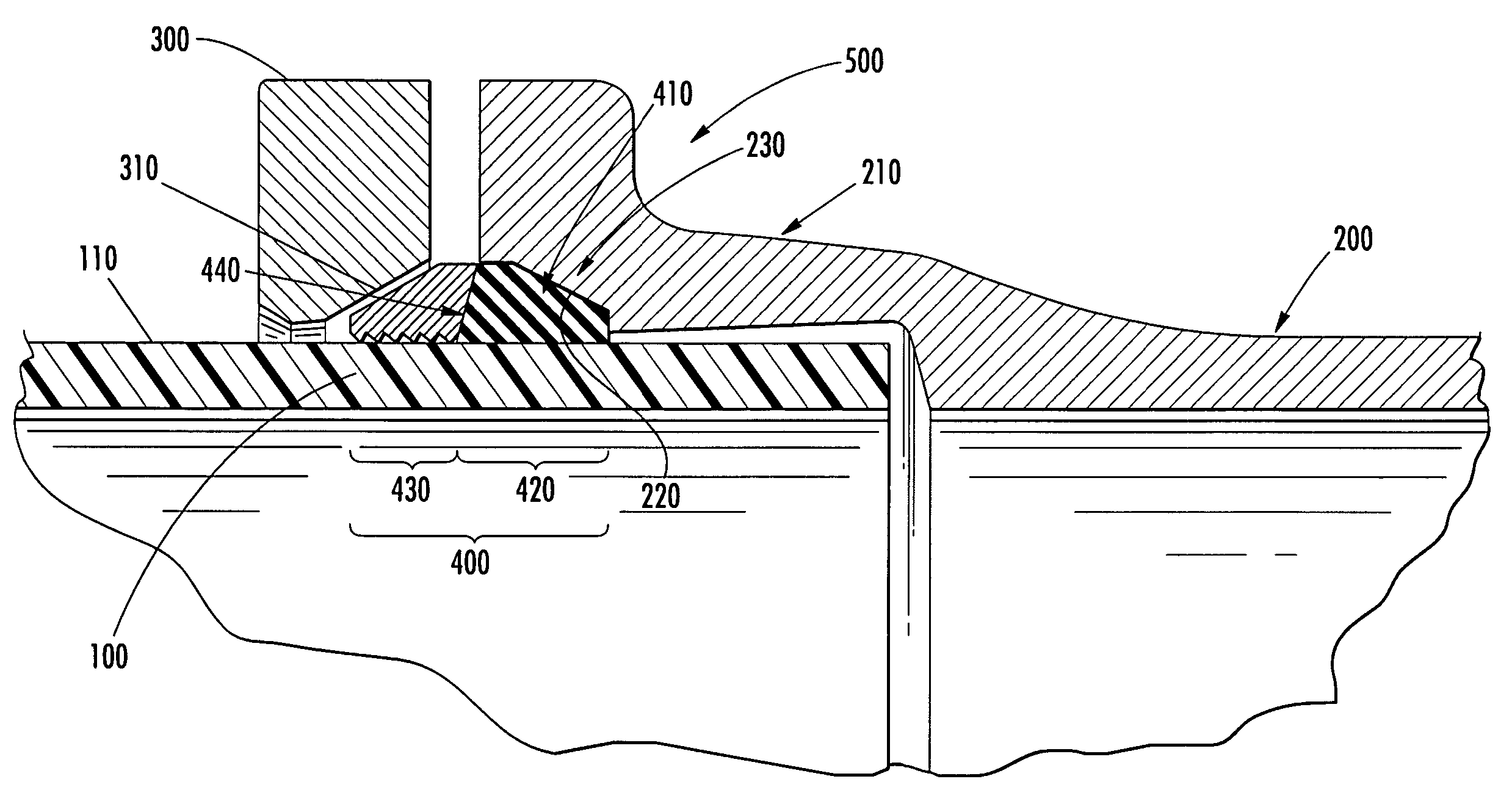
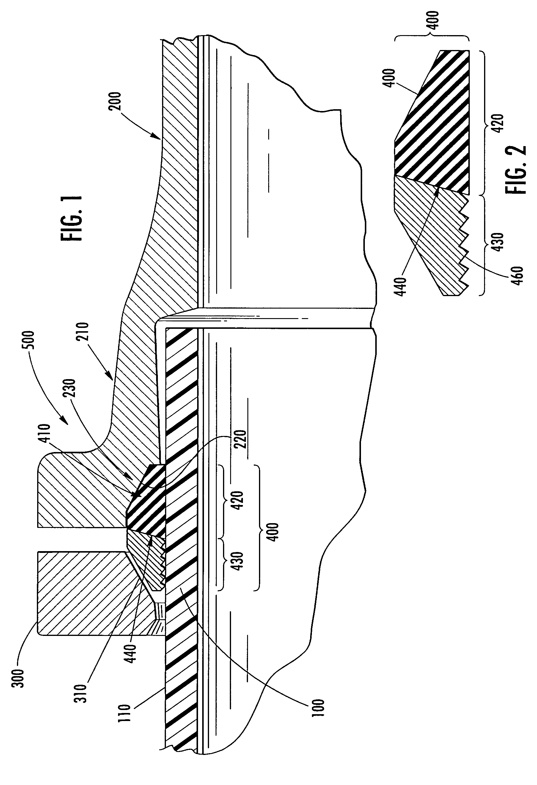
[0029] Referring to FIG. 1, the mechanical pipe joint, restraining gasket and method embodiments of the present invention will be primarily described in conjunction with mechanical pipe joints suitable for round cross-section fluid pipelines. It should be understood, however, that the mechanical pipe joint, restraining gasket and method embodiments of the present invention can be utilized in conjunction with a variety of other applications, both in fluid pipeline conduits and other types of pipelines. For exa...


PUM

PropertyMeasurementUnit
Angleaaaaaaaaaa
Angleaaaaaaaaaa
Angleaaaaaaaaaa

Abstract

A mechanical pipe joint, restraining gasket, and method for restraining pipe spigots within adjacent bell sockets. The restraining gasket is composed of two axially-separate components: a sealing portion and a restraining portion made of a plurality of arcuate locking members. The restraining gasket and a gland surround an outer surface of the pipe spigot. The mechanical pipe joint is formed as the pipe spigot is inserted into the bell socket and the gland is axially attached to the bell socket so that the restraining gasket is held between: the gland, an inner surface of the bell socket, and the outer surface of the pipe spigot, so as to provide a fluid seal in the joint and urge the locking members into contact with the outer surface of the pipe spigot, axially restraining the pipe spigot within the bell socket.

Description

FIELD OF THE INVENTION [0001] The present invention relates generally to mechanical joint connections between pipe spigots and bell sockets and, more particularly, relates to a mechanical pipe joint, gasket and method for more effectively sealing and restraining pipe spigots in mechanical joint bell sockets using a gasket with a sealing portion that is axially separated from a restraining portion, the restraining portion having a plurality of arcuate locking members. BACKGROUND OF THE INVENTION [0002] The construction of pipelines generally involves the axial connection of two pieces of pipe to form a single pipeline conduit for transporting materials from one point to another. Along the pipeline there may be one or more fittings, which allow the pipe pieces to be joined to other components in the pipeline. The liquid or gaseous materials usually conveyed via pipelines require that the pipeline conduits and joints between axially-joined pieces of pipe, and between pipes and fittings...

Claims


Application Information

Patent Timeline
IPC IPC(8): F16L19/07F16L21/04F16L21/08F16L47/12
CPCF16L21/04Y10S285/91F16L47/12F16L21/08
Inventor OWEN, WILLIAM H.HOLMES, WILLIAM W. IVCOPELAND, DANIEL A.
Owner US PIPE & FOUNDRY
Learn More