
Fuel supply apparatus for engine and method thereof

a technology for fuel supply apparatus and engine, which is applied in the direction of positive displacement liquid engine, electric control, piston pump, etc., can solve the problems of deterioration of combustion characteristics, and increase of emission due to short fuel injection time, so as to avoid deterioration of combustibility and increase of emission, reduce the effect of fuel supply pressure and lowering fuel supply pressur

Inactive Publication Date: 2005-10-20
HITACHI LTD
View PDF10 Cites 21 Cited by
  • Summary
  • Abstract
  • Description
  • Claims
  • Application Information

AI Technical Summary

Benefits of technology

[0011] Then, an object of the present invention is to avoid a deterioration in the combustibility and an increase in the emission due to a delay in lowering a fuel supply pressure by providing a fuel supply apparatus and a supply method which can actively lower a fuel supply pressure with a simple system.

Problems solved by technology

Then, when a fuel pressure is higher than a target, in some cases, the combustibility deteriorates due to the injection characteristic from the fuel injection valve being varied.
Further, when a fuel pressure is higher than a target, in some cases, a precision in measuring the fuel deteriorates, and the emission increases due to a fuel injection time being made short.
Here, when a route for returning fuel from the fuel pipe to the fuel tank is provided in order to actively lower a fuel pressure, there is the problem that the cost of the fuel supply apparatus rises.

Method used


Image

  • Fuel supply apparatus for engine and method thereof
  • Fuel supply apparatus for engine and method thereof
  • Fuel supply apparatus for engine and method thereof

Examples


Embodiment Construction

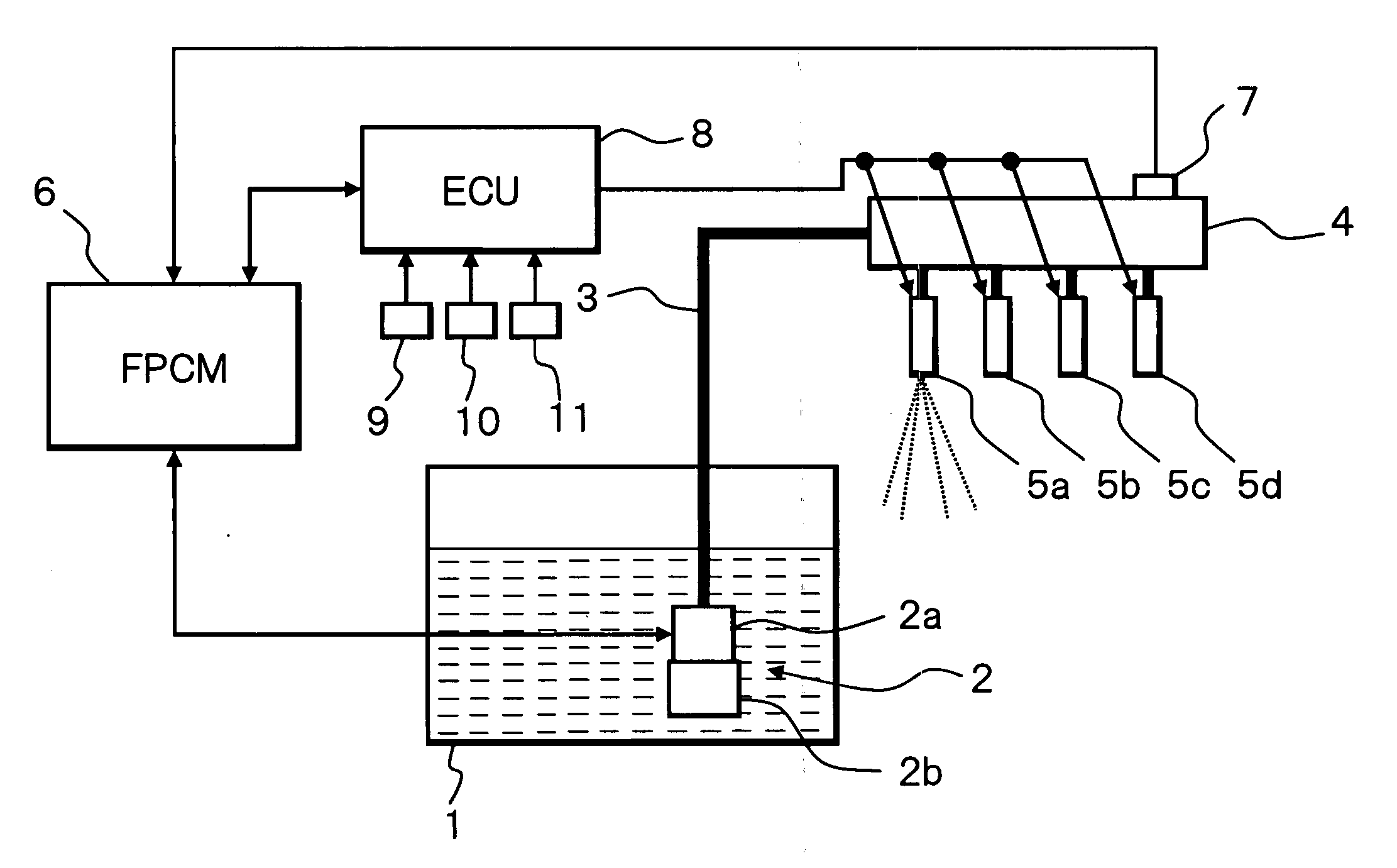
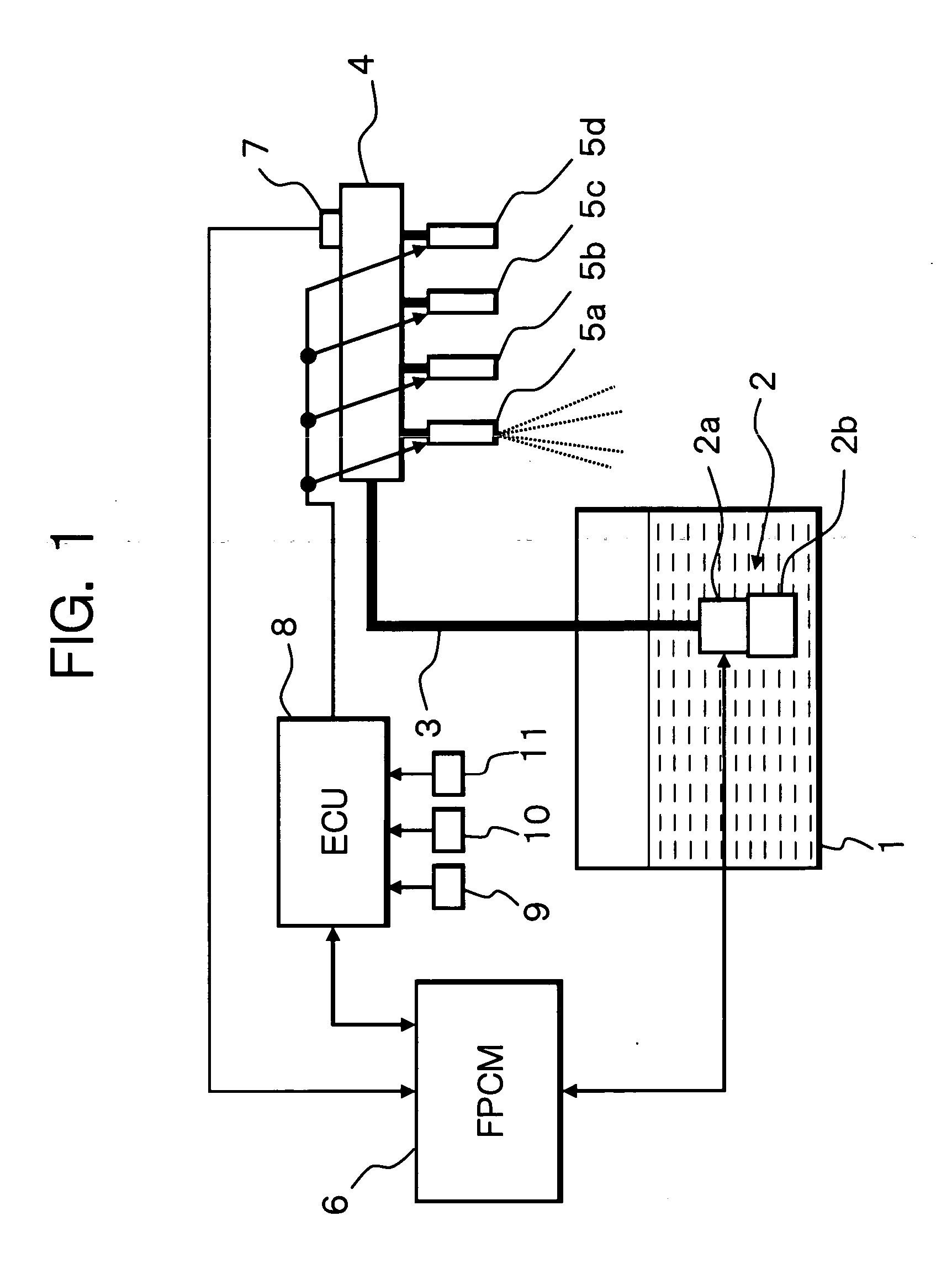
[0016]FIG. 1 is a system diagram showing a fuel supply apparatus in an embodiment of the present invention.

[0017] As shown in FIG. 1, a fuel pump 2 is built in a fuel tank 1.

[0018] Fuel pump 2 sucks and pressurizes fuel in fuel tank 1, and supplies the fuel to fuel injection valves 5a through 5d provided at each cylinder of an internal combustion engine (a gasoline engine) via a fuel pipe 3 and a fuel gallery 4.

[0019] Fuel injection valves 5a through 5d inject the fuel to intake ports of the respective cylinders or into the cylinders of the engine.

[0020] Fuel pump 2 includes a brushless motor 2a and a pump unit 2b driven by brushless motor 2a.

[0021] In the present embodiment, as will be described later, the rotational direction of fuel pump 2 is switched to a normal direction and a reverse direction. Here, due to brushless motor 2a being used as a power source, the reverse driving of fuel pump 2 can be easily realized, and further, the control of a discharge quantity of fuel pu...


PUM


Abstract

When a pressure of fuel supplied to an engine is higher than a target, the fuel is carried in a reverse direction by rotating a fuel pump in reverse, and in accordance therewith, the fuel pressure is made to fall with good responsiveness.

Description

BACKGROUND OF THE INVENTION [0001] 1. Field of the Invention [0002] The present invention relates to a technology of controlling a pressure of fuel supplied to an engine. [0003] 2. Description of the Related Art [0004] There is described as a fuel supply apparatus which supplies fuel from a fuel tank to a fuel injection valve by a fuel pump as described in Japanese Unexamined Patent Publication No. 11-247695. [0005] In the fuel supply apparatus, feedback control in which a target current is set in accordance with a target fuel pressure, and a driving current of the fuel pump is made to coincide with the target current is carried out. [0006] By the way, in a conventional fuel supply apparatus, means for actively lowering a fuel pressure is not provided. [0007] Therefore, for a request to lower a fuel pressure, there has been no means but to wait for that the fuel is removed from a fuel pipe due to the fuel injection from the fuel injection valve. [0008] Accordingly, under the conditi...

Claims


Application Information

Patent Timeline
Patent Type & Authority Applications(United States)
IPC IPC(8): F02M37/08F02D41/38F02M37/04F02M63/02
CPCF02D41/3082F02M63/0225F02D41/3845
Inventor HOSOYA, HAJIME
Owner HITACHI LTD
Learn More