Aircraft having a fuel cell

a fuel cell and aircraft technology, applied in the field of aircraft, can solve the problems of comparatively high proneness to defects and the technical regulation effort associated with their use, and achieve the effect of low proneness to defects and simple structur

Inactive Publication Date: 2010-09-21
LIEBHERR AEROSPACE LINDENBERG
View PDF15 Cites 7 Cited by
  • Summary
  • Abstract
  • Description
  • Claims
  • Application Information

AI Technical Summary

Benefits of technology

[0003]It is therefore the object of the invention to further develop an aircraft, in particular an airplane, of the initially named kind such that the means of influencing the fuel flow have a simple structure and a low proneness to defects.
[0006]Deviating from previously known systems, the fuel cell in accordance with the invention is thus not operated at a constant mass flow or volume flow which is adjusted via a controller comparatively prone to defects, but the fuel cell is operated at a constant pressure for whose setting a pressure regulator or pressure reducer arranged upstream of the fuel cell serves which reduces the supply pressure to the operating pressure of the fuel cell. A restrictor is located downstream of the fuel cell in the associated draining line and reduces the flow of the fuel flowing through the exhaust line and ensures that too large a flow through the fuel cell is not present downstream of the restrictor even at a low pressure.
[0011]The named further fuel supply can be an oxygen supply or an air supply, for example in the form of a tank or of a line. The volume flow, which is larger due to the circuit guidance, has the effect that water arising on the cathode side of the fuel cell is removed particularly effectively.
[0012]In a preferred aspect of the invention, a pressure regulator is also provided in the further supply line and reduces the pressure of the further fuel supply to the operating pressure of the fuel cell or regulates it to the set value.

Problems solved by technology

The disadvantage of such flow regulators is a comparatively high proneness to defects and the technical regulation effort associated with their use.

Method used


Image

  • Aircraft having a fuel cell
  • Aircraft having a fuel cell

Examples


Embodiment Construction

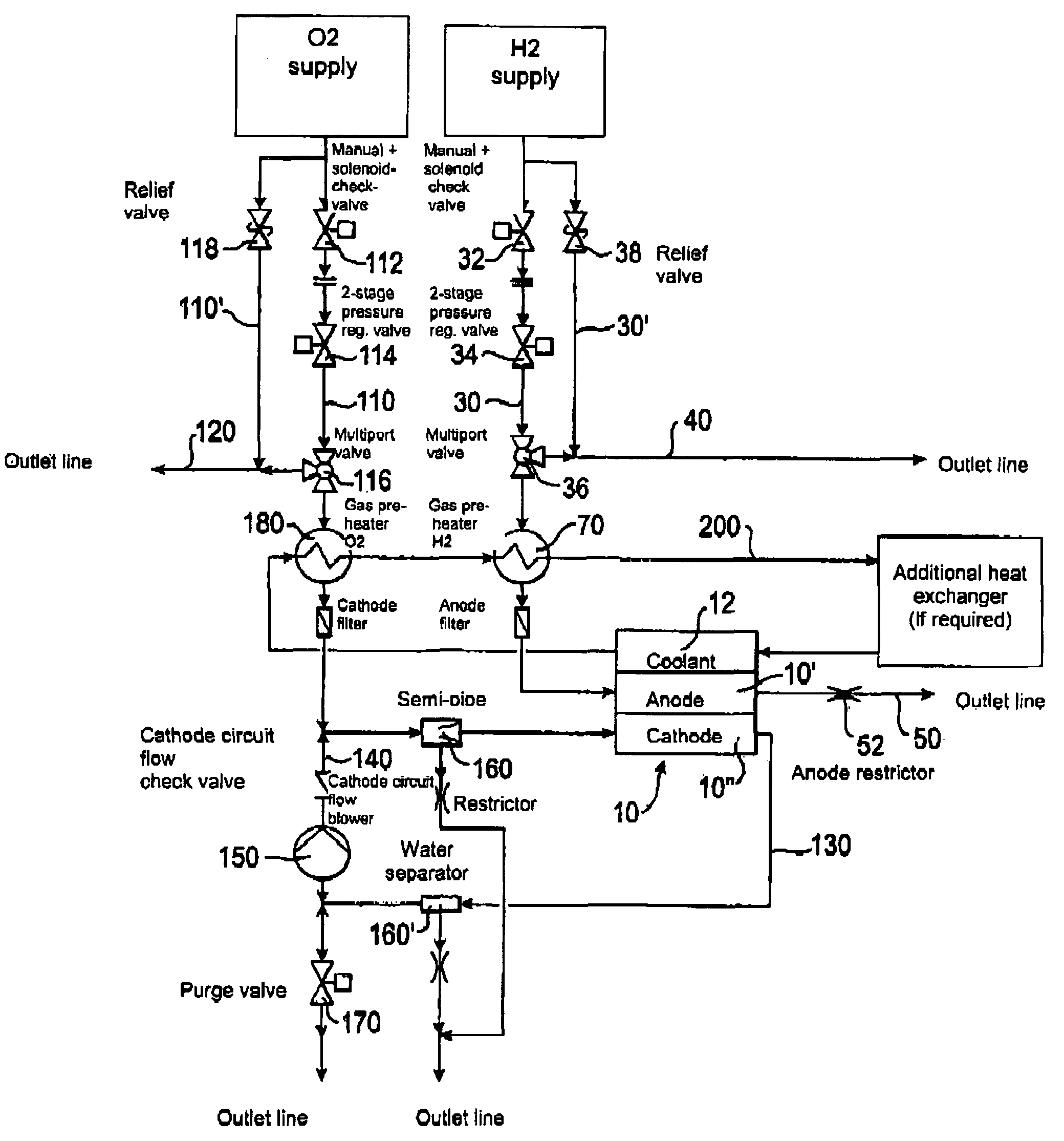
[0028]The reference numeral 10 characterizes the one anode 10′ and a PEM fuel cell 10 having a cathode 10″.

[0029]The anode side 10′ of the fuel cell 10 is supplied with hydrogen from the hydrogen pressure tank (H2 supply). It is in communication with the anode 10′ of the fuel cell 10 via the supply line 30. The valve 32, which is an on / off valve, is located downstream of the hydrogen tank. The pressure regulation valve 34, which is a two-stage pressure reducer, is located downstream of the valve 32. This serves to reduce the high pressure prevailing in the hydrogen tank to the operating pressure of the anode side 10′ of the fuel cell 10. The multiport valve 36 (“on / off vent valve”) is located downstream of the pressure regulation valve 34 and connects the hydrogen tank to the anode 10′ of the fuel cell 10 in one position and the hydrogen tank to the exhaust line or bypass line 40 in a further position.

[0030]The fuel cell 10 is preferably a stack of PEM cells (PEM: proton exchange me...


PUM

PropertyMeasurementUnit
pressureaaaaaaaaaa
constant pressureaaaaaaaaaa
operating pressureaaaaaaaaaa

Abstract

The invention relates to an aircraft, in particular to an airplane, having at least one fuel cell, having at least one supply line which connects the fuel cell to a fuel supply, having at least one outlet line by means of which fuel supplied by the supply line and not consumed in the fuel cell is drained off and having means for the influencing of the fuel flow through the fuel cell as well as having means for the influencing of the fuel flow through the fuel cell, with the means for the influencing of the fuel flow having a pressure regulator located in the at least one supply line and a restrictor member located in the at least one outlet line, with the pressure regulator regulating the pressure of the fuel supply to the operating pressure of the fuel cell and with the restrictor member reducing the flow of the fuel flowing through the outlet line.

Description

BACKGROUND OF THE INVENTION[0001]The invention relates to an aircraft, in particular to an airplane, having at least one fuel cell, having at least one supply line which connects the fuel cell to a fuel supply, having at least one outlet line by means of which fuel supplied by the supply line and not consumed in the fuel cell is drained off and having means for the influencing of the fuel flow through the fuel cell.[0002]The use of fuel cells in aeronautics is known. The fuel cells deliver electrical energy which can be utilized to drive different components of an aircraft. The advantage of the use of fuel cells is an efficiency which is improved with respect to conventional systems with reduced pollution and noise emissions. In fuel cells known from the art, the supply of the fuels to the fuel cell takes place by means of supply lines which are in connection with a corresponding fuel supply. In this process, flow regulators, generally so-called mass flow controllers, are located in...

Claims


Application Information

Patent Timeline
Patent Type & Authority Patents(United States)
IPC IPC(8): H01M8/06H01M8/04
CPCH01M8/04029H01M8/04089B64D2041/002B64D2041/005Y02E60/50Y02T90/36Y02T90/40
Inventor METZLER, DIRKBRUGGER, RALF
Owner LIEBHERR AEROSPACE LINDENBERG
Why Eureka
Try Eureka