
Sprinkler assembly

A sprinkler and component technology, applied in the field of sprinkler components that reduce energy consumption, can solve problems such as large energy consumption or water head loss

Active Publication Date: 2008-05-21
VIKING
View PDF3 Cites 7 Cited by
  • Summary
  • Abstract
  • Description
  • Claims
  • Application Information

AI Technical Summary

Problems solved by technology

This results in considerable energy consumption or head loss for the fluid at the sprinkler assembly

Method used


Image

  • Sprinkler assembly
  • Sprinkler assembly
  • Sprinkler assembly

Examples


Embodiment Construction

[0071] The following description is merely exemplary in nature and is not intended to limit the invention, its application or uses. It should be understood that throughout the drawings, corresponding reference numerals indicate like or corresponding parts and features.

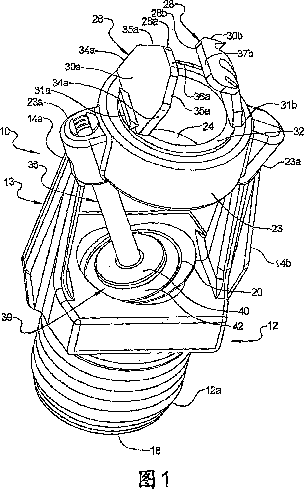
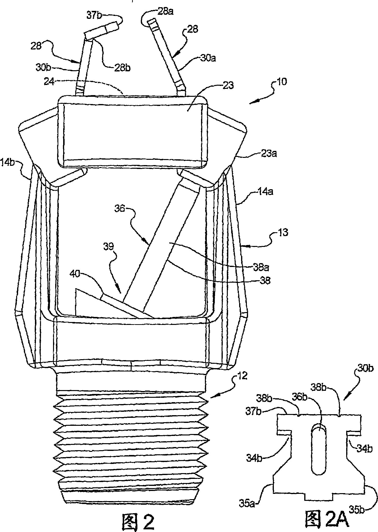
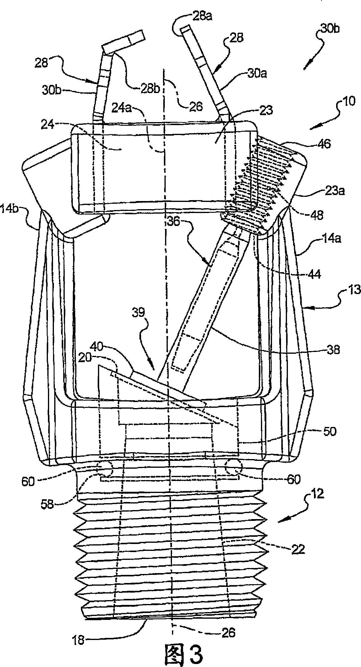
[0072] Referring to Figure 1, the numeral 10 generally designates the sprinkler assembly of the present invention. As will be described more fully below, the sprinkler assembly 10 is constructed and arranged to reduce fluid energy consumption when fluid flows from the sprinkler assembly 10 . The term "fluid" is used in this application in its broadest sense and includes substances capable of flowing such as water, foam, water / foam mixtures, gases, powders, and other known fire suppression materials. In the illustrated embodiment, the sprinkler assembly 10 is shown as a sidewall type sprinkler assembly 10; however, as will be more fully understood from the description below, the sprinkler assembly of the prese...


PUM


Abstract

A sprinkler assembly includes a body, a support, which extends from the body, and a closure device that releasably closes the discharge opening of the body. The sprinkler assembly further includes a trigger that releasably holds the closure device at the discharge opening. The support is adapted to allow the fluid flowing from the discharge opening, when the closure device is released, to pass through the support substantially unimpeded by the support and, further, is adapted to reshape the flow of fluid as it flows through the support.

Description

technical field [0001] The present invention relates to a sprinkler assembly, and more particularly, to a sprinkler assembly that reduces energy consumption for use in residential and commercial applications, including warehouse applications, and that can be used in used in control mode or inhibit mode. Background technique [0002] The statements in this section merely provide background information related to the present disclosure and may not constitute prior art. [0003] Significant energy consumption occurs on the sprinkler assembly that distributes the fluid. A conventional sprinkler assembly includes a base having a channel, an inlet and an outlet, and a deflector typically supported by and spaced from a pair of arms extending from the base, adapted for connection to system piping. The arms are often connected at the ends by lugs which are used to mount the deflectors to the arms. Pendant and upright sprinklers typically include a deflector having a solid central ...

Claims


Application Information

Patent Timeline
Patent Type & Authority Applications(China)
IPC IPC(8): B05B1/26
CPCB05B1/265B05B1/267A62C37/08
Inventor 斯科特·托马斯·弗兰森托马斯·埃德加·瓦恩布雷纳肖恩·格里戈里·奥尔
Owner VIKING
Learn More