Catalyst temperature modelling during exotermic operation

a catalytic converter and temperature modelling technology, applied in the direction of electrical control, exhaust treatment electric control, instruments, etc., can solve the problems of limited absorption capacity of storage catalysts, limited absorption capacity of particulate filters, and need to be regenerated regularly,

Inactive Publication Date: 2005-10-13
ROBERT BOSCH GMBH
View PDF9 Cites 37 Cited by
  • Summary
  • Abstract
  • Description
  • Claims
  • Application Information

AI Technical Summary

Benefits of technology

[0009] According to an example embodiment of the present invention, a method and a device for calculating the catalytic converter temperature may make possible the calculation of the catalytic converter temperature in normal operation without subsequent exothermic regeneration taking place and in operations having subsequent regeneration of the catalytic converter.
[0014] As a result, both undesired HC emissions and undesired high thermal loads of the exhaust gas treatment system may be avoided thereby. This may be achieved by a calculation on the basis of operating parameters, which are present in a control unit in any case. Therefore, one may do without a costly temperature sensor, which may be positioned such that it records the temperature at the location of a possible exothermic reaction, that is, in the catalytic converter itself.
[0018] This arrangement may take into consideration that the catalytic converter activity and therewith the extent of the heat generated in a catalytically triggered exothermically occurring reaction in the catalytic converter is a function of the temperature of the catalytic converter or the exhaust gas aftertreatment system. As a result, because of the taking into consideration of this influence, the accuracy of modeling the temperature may be increased.
[0024] This arrangement may take into consideration that the heat becoming liberated in an exothermic reaction in the catalytic converter is not only a function of a fuel mass that is available for such an exothermic reaction, but also of the oxygen quantity that is available in the exhaust gas. In addition, this arrangement may provide how the oxygen quantity that is available may be formed from operating parameters that are present in any case in the control unit of the internal combustion engine. In this manner, the heat becoming liberated in an exothermic reaction and the temperature rise connected with it may be accurately determined if the air quantity available for the reaction is not sufficient for utilizing the total second fuel mass available for the reaction. The control unit may in this case, for example, and beyond the already described aspects, take care that the second fuel mass is diminished in successive injections, in order to prevent liberation of HC emissions into the environment, or at least to lower them.
[0029] These quantities may bring about a response of the time constant which may lead to good results of the temperature modeling in the PT1 filtering.

Problems solved by technology

It is true that the absorption capability of storage catalysts is limited, so that these storage catalysts have to be regularly regenerated in order to become absorptive for nitrogen oxides again.
Even these particulate filters have a limited absorptive capacity and also have to be regenerated regularly.
In addition, because of that, uncombusted hydrocarbons may also be emitted into the environment.

Method used


Image

  • Catalyst temperature modelling during exotermic operation
  • Catalyst temperature modelling during exotermic operation
  • Catalyst temperature modelling during exotermic operation

Examples


Embodiment Construction

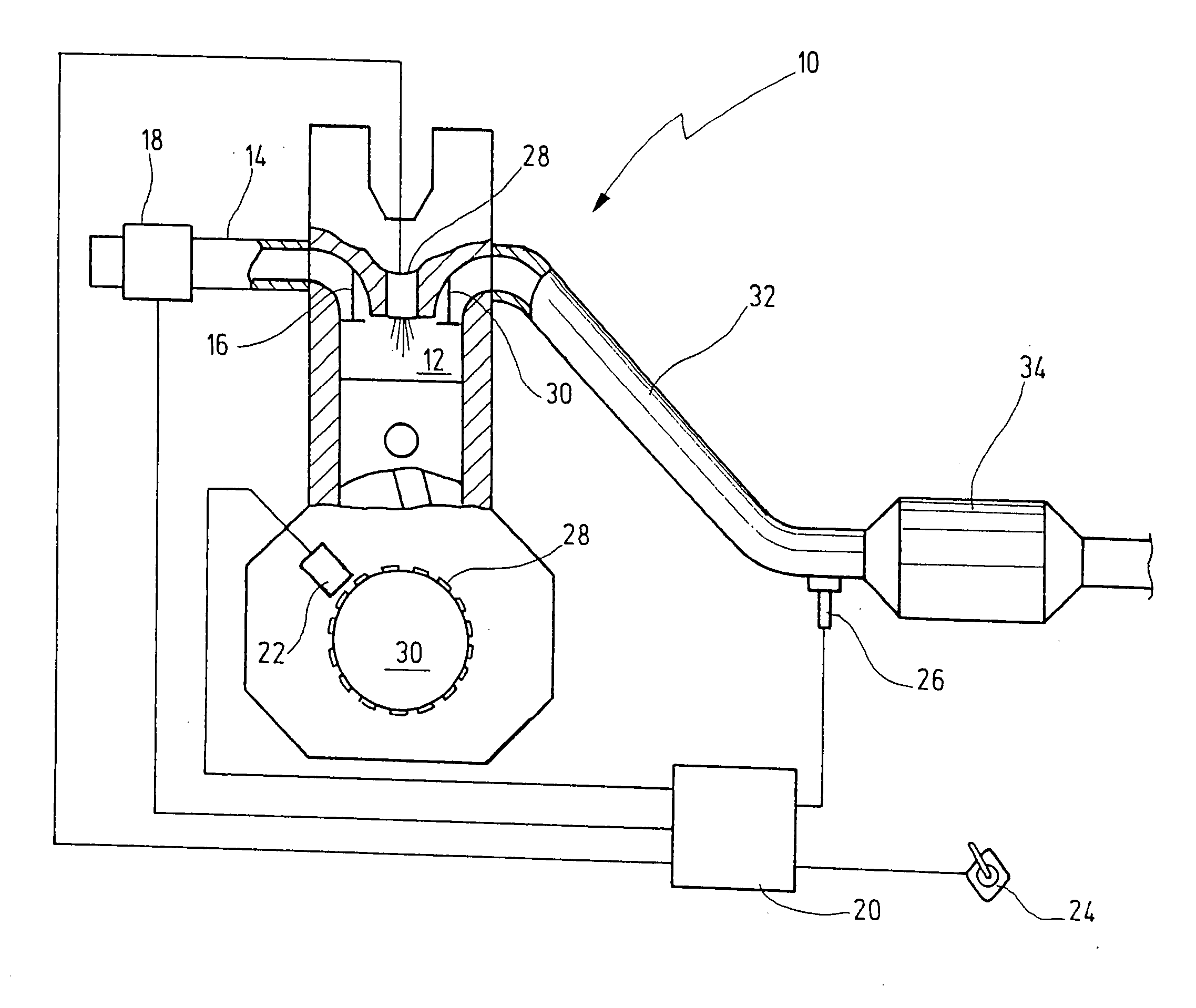
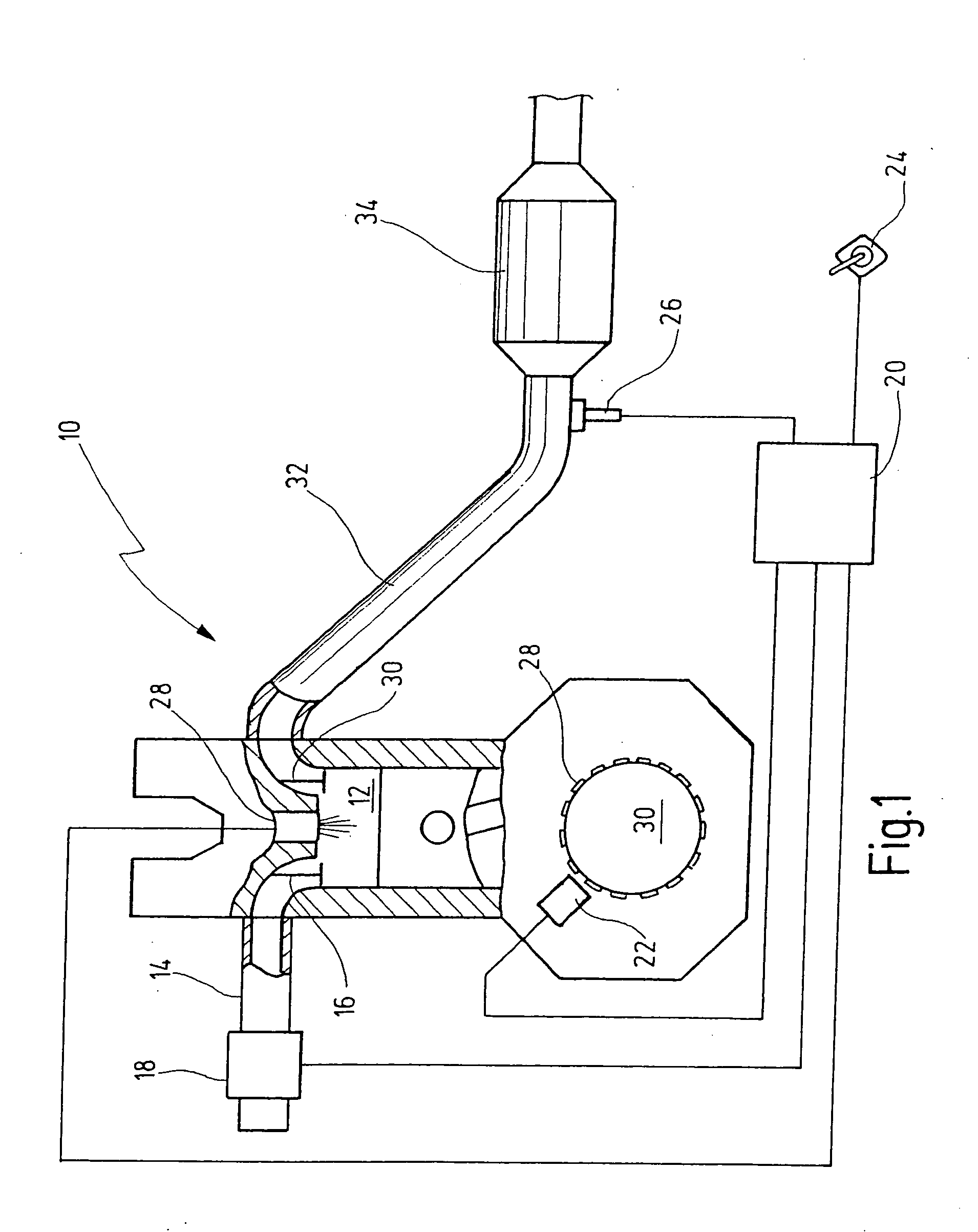
[0036] The number 10 in FIG. 1 denotes an internal combustion engine having a combustion chamber 12 in which a mixture of fuel and air is combusted. Combustion chamber 12 has air supplied to it via a vacuum line 14, the air supply being controlled by at least one intake valve 16. The mass of air taken in by internal combustion engine 10 is recorded by an air mass flow sensor 18, which passes on an air mass signal to calculating device 20, such as an electronic control unit. The signals of additional sensors are supplied to calculating device 20, of which FIG. 1 illustrates a rotary speed sensor 22, an accelerator sensor 24 and an exhaust gas sensor 26.

[0037] Signals of additional sensors, for example, concerning temperatures in the region of the internal combustion engine or concerning the transmission ratio of a post-connected torque converter, etc., may also be supplied to calculating device 20. Rotary speed sensor 22 illustrated in FIG. 1 may, for example, be an inductive sensor...


PUM


Abstract

A method and a calculating device are for modeling the temperature of a catalytic converter in the exhaust gas of an internal combustion engine. In this context, the heat input into the catalytic converter based on exothermic reactions is taken into consideration. The method provides that a first correcting quantity delta_T1 and a second correcting quantity delta_T2 are formed, which each take into consideration a heat input into the catalytic converter based on exothermic reactions in the catalytic converter, delta_T1 being formed as a function of the ratio of the first fuel mass, combusted in the internal combustion engine simultaneously with an air mass, to the air mass, and delta_T2 being formed as a function of a heat input that results from an exothermic reaction of a second fuel mass, which was metered in for the regeneration of the catalytic converter in addition to the fuel proportion of the fuel / air mixture combusted in the internal combustion engine.

Description

FIELD OF THE INVENTION [0001] The present invention relates to a method for calculating the temperature of a catalytic converter in the exhaust gas of an internal combustion engine. The method may include: forming a base value for the temperature of the catalytic converter; calculating a correcting quantity delta-T1 which takes into consideration the heat input into the catalytic converter based on exothermic reactions in the catalytic converter, and which is a function of the ratio of the first fuel mass combusted in the internal combustion engine simultaneously with an air mass and of the exhaust gas temperature; and filtering a value correlated to a catalytic converter temperature using low-pass filtering and forming a new value for the temperature of the catalytic converter, taking into consideration the base value and the result of the low-pass filtering. [0002] The present invention also relates to a calculating device for calculating the temperature of a catalytic converter i...

Claims


Application Information

Patent Timeline
IPC IPC(8): F01N9/00F02D41/02F02D41/40
CPCF01N9/005F02D41/025F02D41/0255F02D41/029Y02T10/47F02D2200/0804Y02T10/44Y02T10/26F02D41/405Y02T10/12Y02T10/40
Inventor MANSBART, MATTHIAS
Owner ROBERT BOSCH GMBH
Why Eureka
Try Eureka