
Power semiconductor switching-device and semiconductor power module using the device

a technology of switching device and semiconductor power module, which is applied in the direction of mechanical equipment, machines/engines, pulse techniques, etc., can solve the problems of increasing the surge voltage applied to the gate, and achieve the effect of small size and low manufacturing cos

Active Publication Date: 2005-10-13
DENSO CORP
View PDF6 Cites 27 Cited by
  • Summary
  • Abstract
  • Description
  • Claims
  • Application Information

AI Technical Summary

Benefits of technology

[0007] In view of the above problems, it is an object of the present invention to provide a semiconductor power module that can be fabricated at a low manufacturing cost and a small size while maintaining power sufficient to endure a surge voltage.

Problems solved by technology

First, the gate series resistor has an effect of attenuating a surge voltage applied to the gate on an oxide film having easily been damaged insulation from an external source by way of the control input terminal of the semiconductor power module similarly to the conventional power semiconductor chip.
Thus, the conventional power semiconductor module raises a problem that a surge voltage applied to the gate increases.

Method used


Image

  • Power semiconductor switching-device and semiconductor power module using the device
  • Power semiconductor switching-device and semiconductor power module using the device
  • Power semiconductor switching-device and semiconductor power module using the device

Examples


Embodiment Construction

[0036] An embodiment of the present invention is explained by referring to diagrams. It is to be noted, however, that the present invention is by no means limited to this embodiment. In addition, the technological concept of the present invention can of course be implemented by using other commonly known technologies.

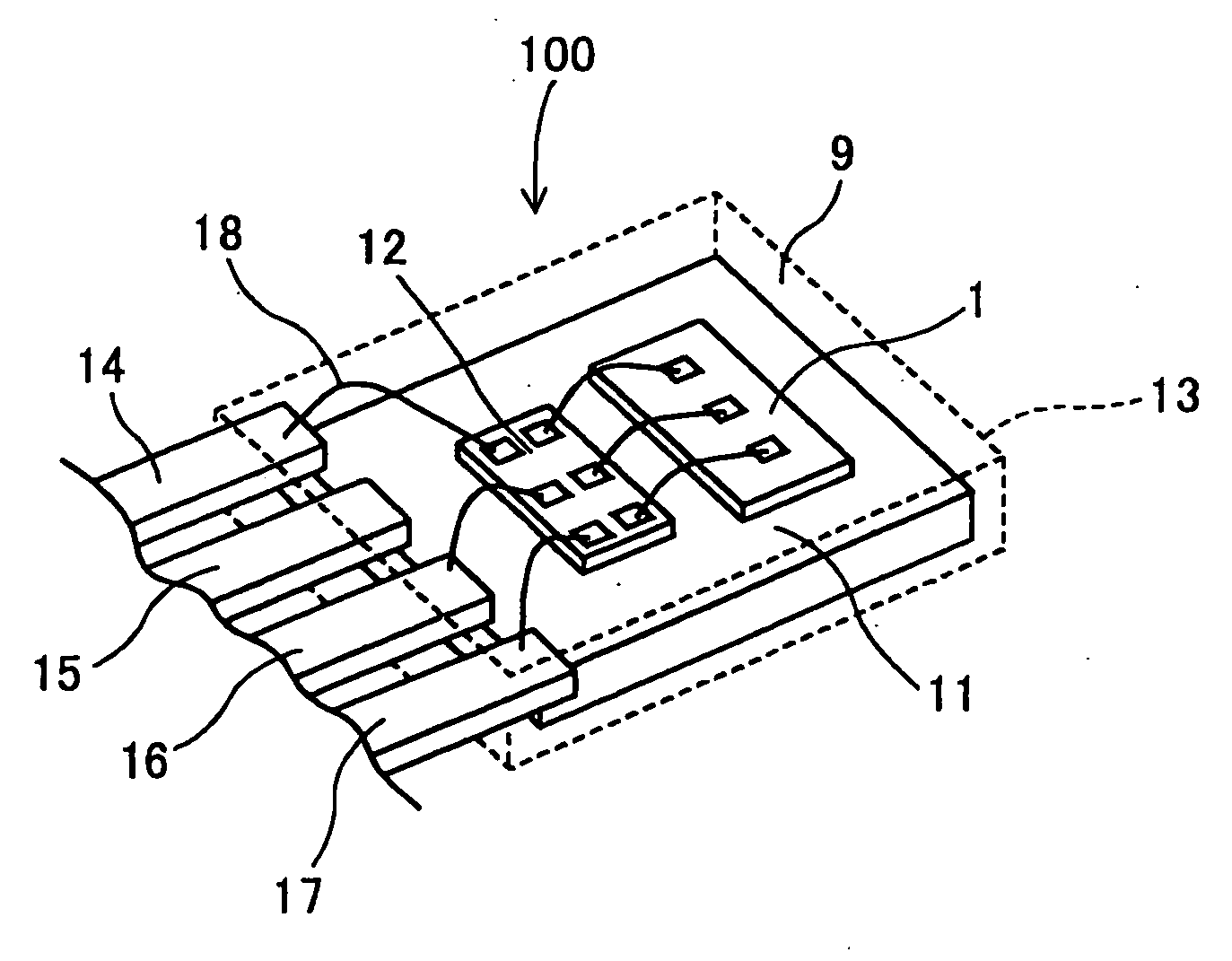
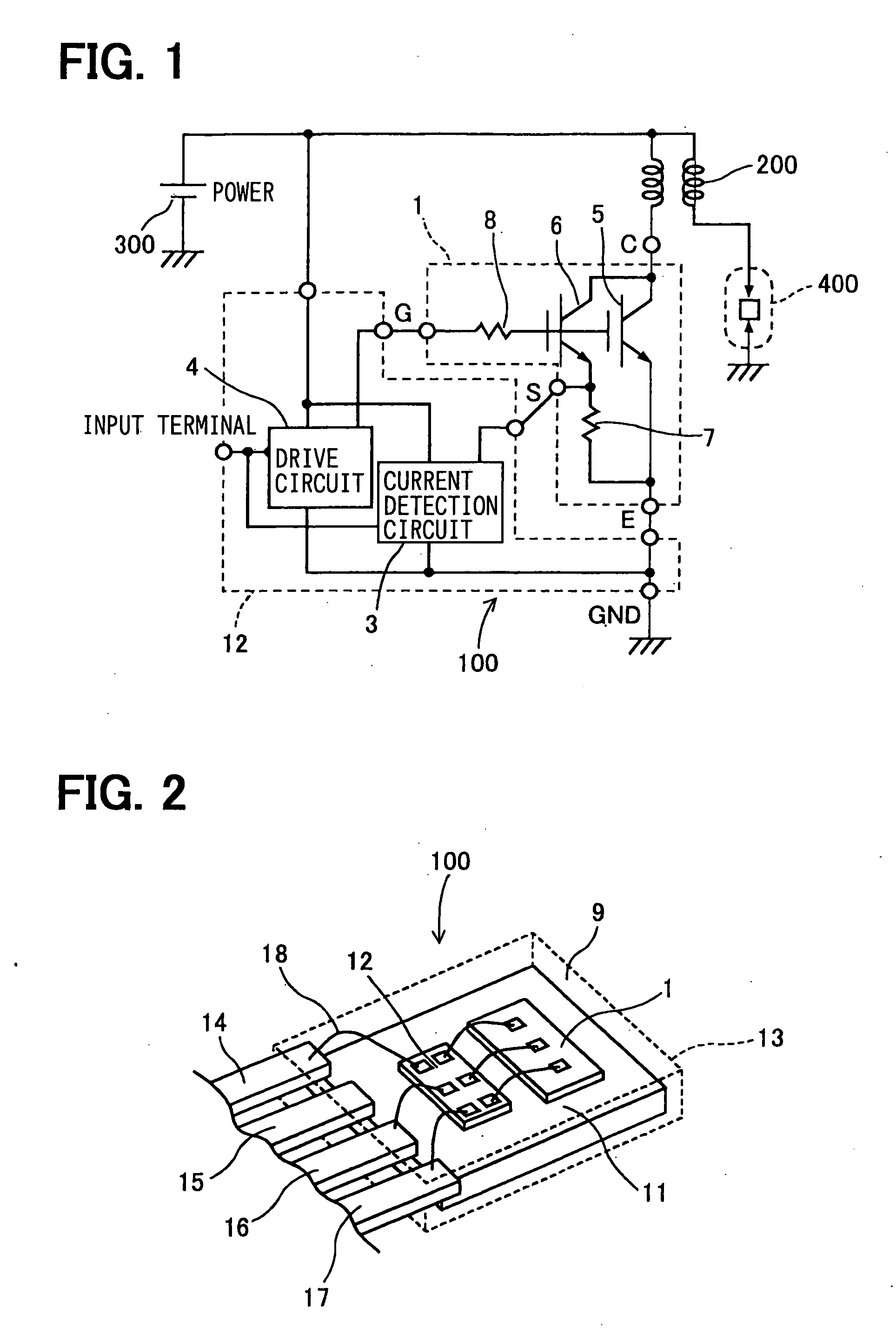
[0037] As an embodiment of a semiconductor power module using a power semiconductor switching-device provided by the present invention, an ignition system using an ignition apparatus employing the semiconductor power module is explained by referring to FIG. 1. A semiconductor power module 100 has a power semiconductor chip 1 and a control semiconductor chip 12. In the control semiconductor chip 12, a current detection circuit 3 and a driving circuit 4 are integrated by using an integrated-circuit technology. The power semiconductor chip 1 is a chip in which a main switch unit 5, a sub-switch unit 6, a current detection resistor 7 and a gate series resistor 8 are integr...


PUM


Abstract

A single semiconductor power module includes a power semiconductor chip including an embedded IGBT (the power semiconductor switching-device) and a control semiconductor chip. The power semiconductor chip also includes a gate series resistor integrated therein as a resistor through which the control semiconductor chip drives the power semiconductor chip. In such a configuration, a gate wire between the gate series resistor and a gate has a small lead inductance and a small parasitic capacitance with respect to the ground.

Description

CROSS REFERENCE TO RELATED APPLICATIONS [0001] This application is based on and incorporates herein by reference Japanese Patent Application No. 2004-115400 filed on Apr. 9, 2004 and Japanese Patent Application No. 2005-31728 filed on Feb. 8, 2005, the contents of both of which are incorporated herein by reference. FIELD OF THE INVENTION [0002] The present invention relates to a power semiconductor switching-device and a semiconductor power module, and, more particularly, to an ignition apparatus using the power semiconductor switching-device and the semiconductor power module. BACKGROUND OF THE INVENTION [0003] A conventional ignition apparatus for supplying power to an ignition coil of an internal combustion engine is implemented by a semiconductor power module as disclosed in JP-2000-179440A (hereafter “patent reference 1”). FIG. 8 is a circuit diagram showing the semiconductor power module disclosed in patent reference 1 and FIG. 9 is a diagram showing a perspective view of a mo...

Claims


Application Information

Patent Timeline
Patent Type & Authority Applications(United States)
IPC IPC(8): H01L25/07H01L23/49H01L23/495H01L25/16H01L25/18H01L29/739H01L29/78H01L29/80H03K17/082H03K17/16
CPCH01L23/49562F02P3/053H01L25/16H01L29/7395H01L2224/48091H01L2224/48137H01L2224/48247H01L2224/49H01L2924/01004H01L2924/01006H01L2924/01013H01L2924/01014H01L2924/01015H01L2924/01052H01L2924/01082H01L2924/13055H01L2924/14H01L2924/19041H01L2924/19042H01L2924/19043H01L2924/30105H01L2924/30107H03K17/0828H03K17/162H01L24/49H01L2924/181H01L2924/00014H01L2924/13091H01L2924/15787H01L2924/01055H01L2924/01043H01L2924/01033H01L2924/01023H01L24/48H01L2924/00H01L2224/45099F02P3/0442H01L2224/05554H01L2924/00012
Inventor YAMAGUCHI, MOTOOKATO, NAOHITOTOMATSU, YUTAKA
Owner DENSO CORP
Learn More