
Bearing unit, and motor and electronic apparatus having the bearing unit

Inactive Publication Date: 2005-10-06
SONY CORP
View PDF10 Cites 12 Cited by
  • Summary
  • Abstract
  • Description
  • Claims
  • Application Information

AI Technical Summary

Benefits of technology

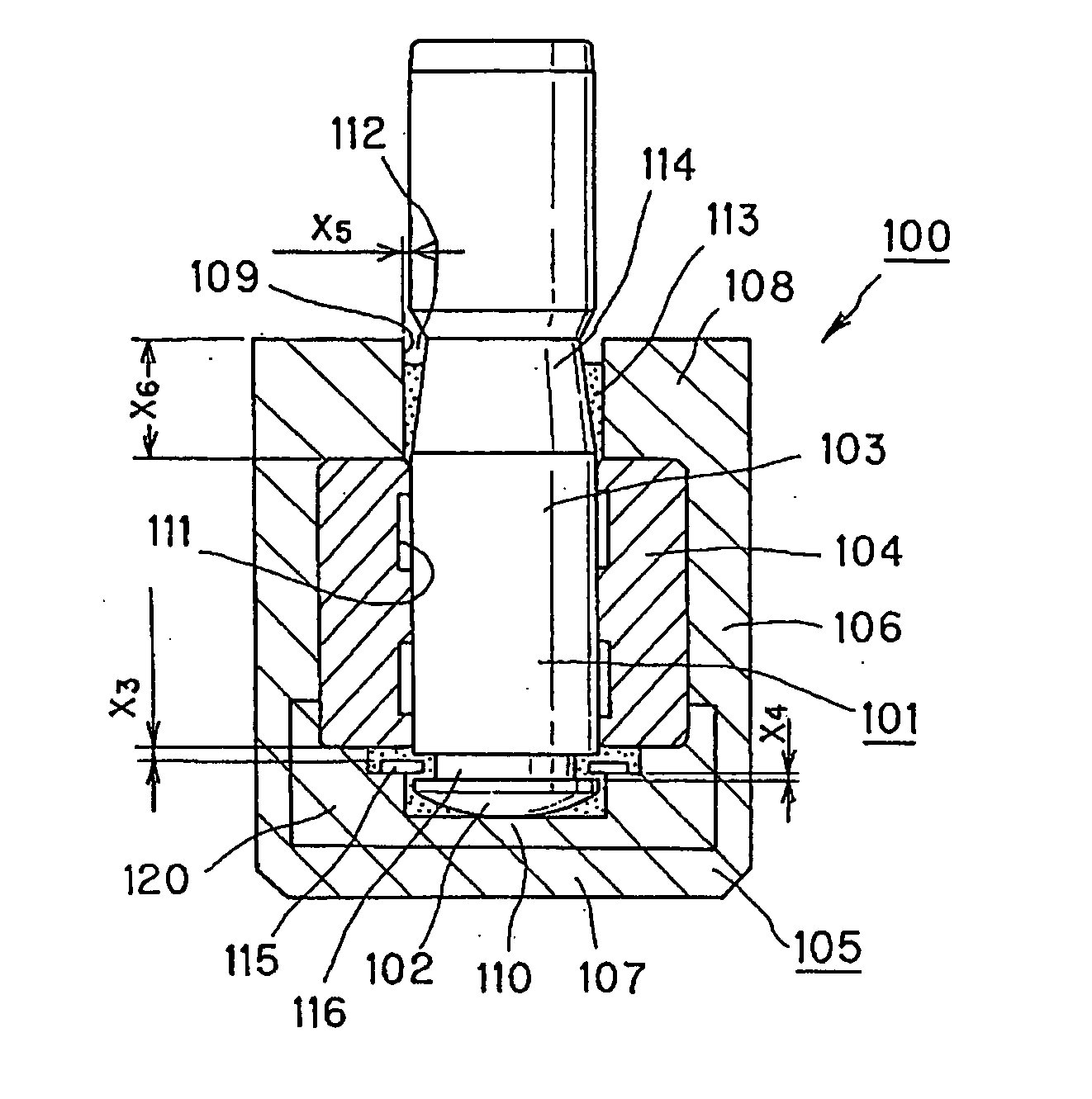
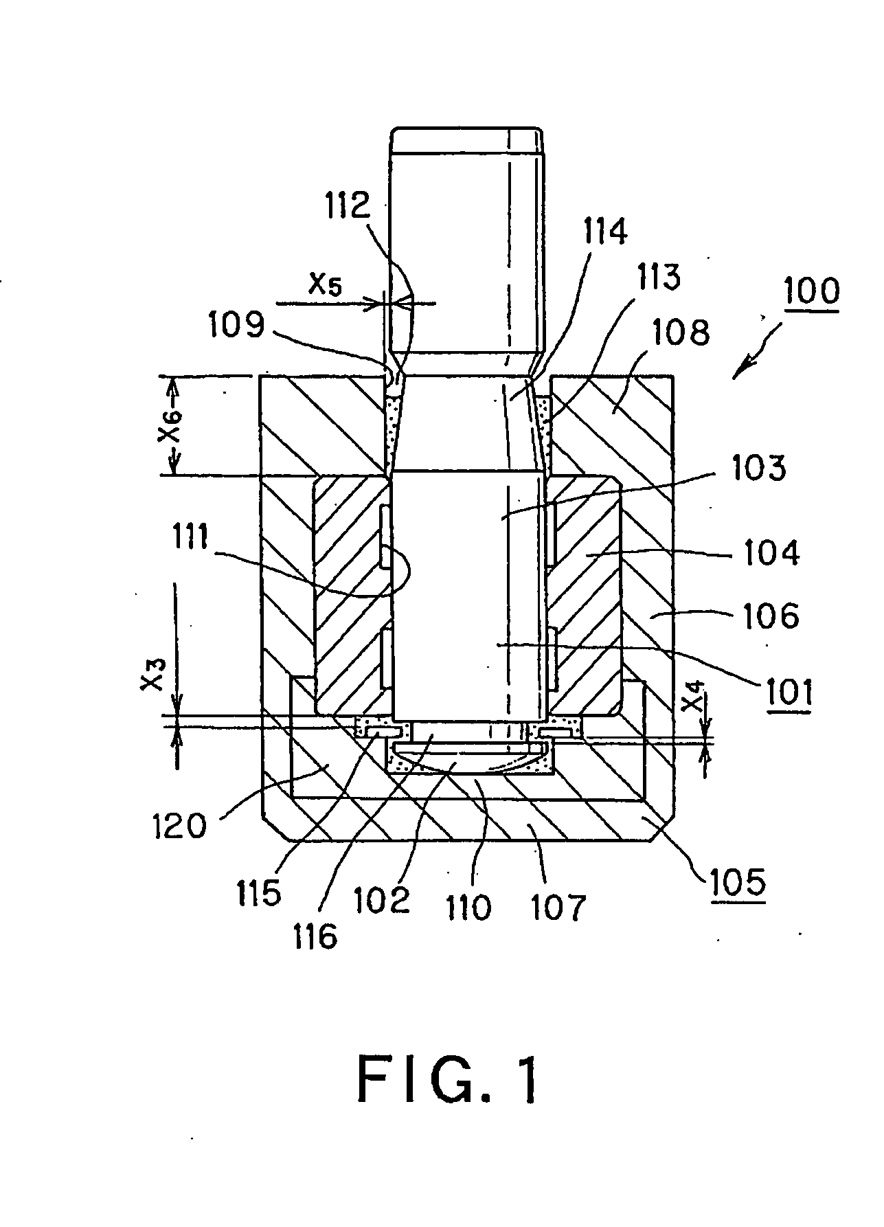
[0022] An object of the present invention is to provide a bearing unit, and a motor and an electronic apparatus each having the bearing unit, wherein a shaft of the bearing unit is prevented from being pulled out from a housing, and the liquid surface of a lubrication oil filled in the housing is prevented from lowering with air mixed into the lubrication oil between a radial bearing and the shaft even when the shaft is pulled out from the housing, so that excellent lubrication can be attained.
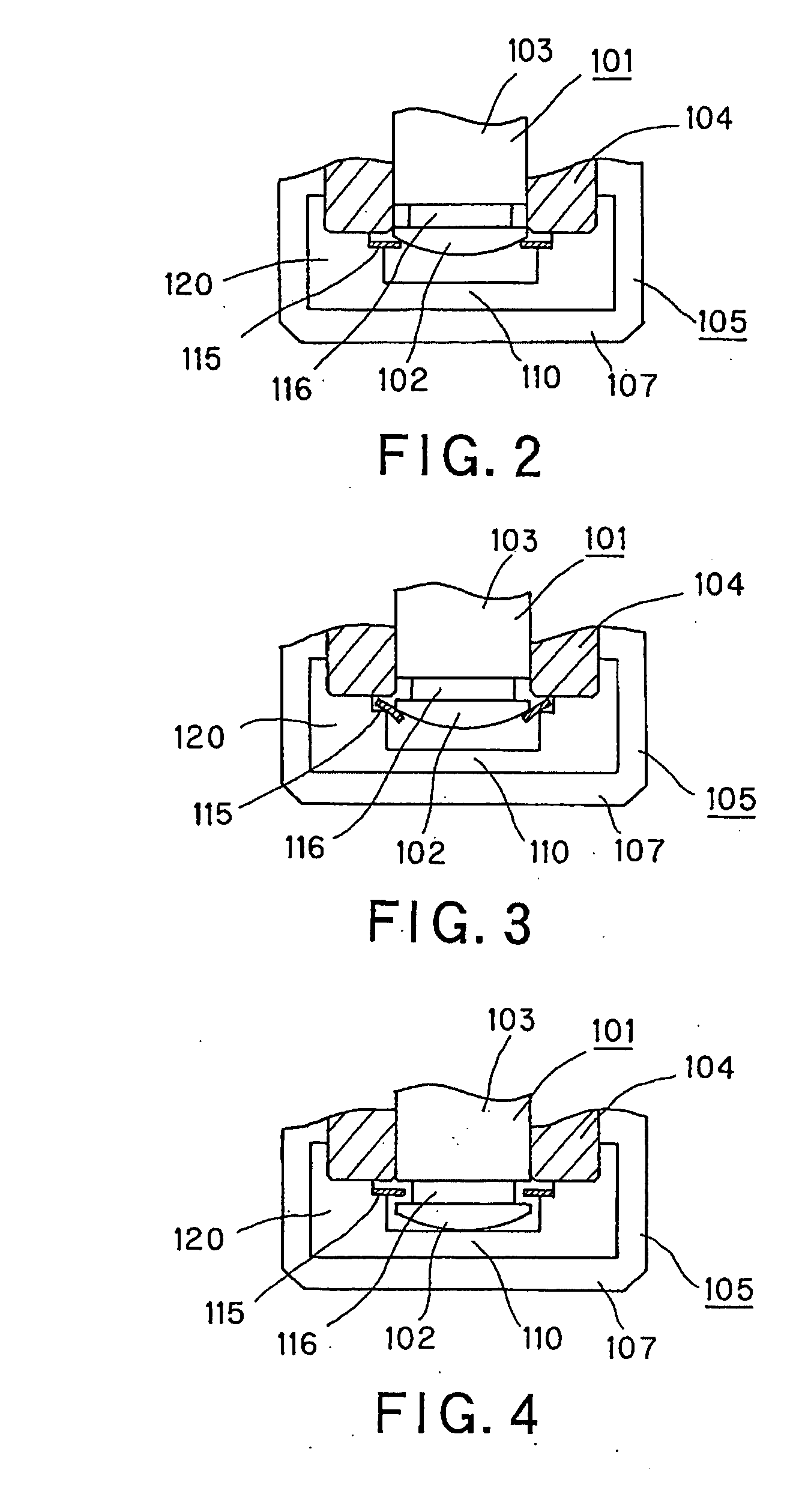
[0024] As described above, in the bearing unit according to the present invention, the stopper member is elastically deformed in the radial direction of the shaft by an end part on the insertion side of the shaft, when the shaft is inserted. Therefore, the stopper member does not obstruct insertion of the shaft. Once the shaft is inserted, the stopper member functions as a stopper which prevents the shaft from falling off or being pulled out of the housing because the stopper member is hardly deformed in the axial direction. As a result of this, movement of the shaft in the axial direction is regulated by the stopper member, so that the shaft is prevented from being pulled out from the housing.
[0025] Further, the stopper member does not have such a structure in which the stopper member is warped in the axial direction to allow the shaft to be inserted when the shaft is inserted, as shown in the prior art. Therefore, it is unnecessary to provide an extra gap which allows the stopper member to be warped in the axial direction when the stopper member is attached. As a result, the shaft is prevented from moving a distance corresponding to the extra gap for allowing the stopper member to be warped, and is accordingly prevented from being pulled out.
[0026] Thus, according to the present bearing unit, the liquid surface of the lubrication oil in the housing is not lowered because of lifting up of the shaft. Further, air is not mixed up in the lubrication oil between the radial bearing and the shaft by such lowering of the liquid surface. In addition, the lubrication oil is not pushed out to cause leakage by such air.
[0029] According to the present invention, there is provided a stopper member made of an elastic member which is elastically deformed only in the radial direction of the shaft when the shaft is inserted and which is hardly deformed in the axial direction. It is therefore possible to extremely reduce the size of the gap between the radial bearing and the stopper member, which allows the shaft to move in the axial direction, and the size of the gap between stopper member and the housing. Accordingly, the shaft is prevented from being pulled out from the housing, so that the liquid surface of the lubrication oil is prevented from lowering due to pulling out of the shaft. As a result, air is prevented from being mixed in the lubrication oil filled between the radial bearing and the shaft, so that the lubrication oil can be steadily maintained between the radial bearing and the shaft.
[0030] Also according to the present invention, the lubrication oil between the radial bearing and the shaft can be maintained steadily for a long time period. Excellent lubrication and excellent rotation performance can be maintained.

Problems solved by technology

This may involve a hindrance to the rotation performance of the bearing unit.
Alternatively, air which has once entered may swell due to influences from the temperature and the air pressure, and the hydraulic oil may leak to the outside of the unit.
However, the widening of the gap x5 may result in leakage of hydraulic oil when the unit is used, placed laterally, or on vibrating impact.

Method used


Image

  • Bearing unit, and motor and electronic apparatus having the bearing unit
  • Bearing unit, and motor and electronic apparatus having the bearing unit
  • Bearing unit, and motor and electronic apparatus having the bearing unit

Examples


Embodiment Construction

[0052] In the following, an information processing apparatus (electronic apparatus) to which the present invention is applied will be explained with reference to the drawings.

[0053] As shown in FIG. 5, the information processing apparatus to which the present invention is applied is a notebook-type personal computer, and has a display unit 2 which displays results of information processing, and a computer body 3 which includes an information processing unit which performs calculation processings on various information. A keyboard 5 for inputting operation commands of the computer 1 or various information is provided on the upper surface side of the computer body 3. A heat radiator 4 is provided therein. The heat radiator 4 radiates, to the outside, heat generated from information processing circuits such as a CPU, a disk device, and the like, which are provided inside the computer body 3. The heat radiator 4 also functions as a cooler which cools down the inside of the computer bod...


PUM


Abstract

The bearing unit of the present invention has: a shaft; a radial bearing which supports the shaft in a circumferential direction of the shaft; a thrust bearing which supports an end of the shaft in a thrust direction of the shaft; a housing having a closed structure except for a shaft insertion hole in which the shaft is inserted, with the radial bearing and the thrust bearing being provided inside the housing; a stopper member which prevents the shaft from being pulled out of the radial bearing; and viscous liquid filled in the housing. The stopper member is made of an elastic member which is elastically deformed only in the radial direction and is hardly deformed in the axial direction. Hence, the shaft is prevented from being pulled out from the housing, and shortage of the lubrication oil around bearing surfaces is prevented from being caused by lifting of the shaft.

Description

BACKGROUND OF THE INVENTION [0001] 1. Field of the Invention [0002] The present invention relates to a bearing unit which rotatably supports a rotation shaft or rotatably supports a rotation member on the shaft, and a motor and an electronic apparatus each having the bearing unit. [0003] This application claims priority of Japanese Patent Application No. 2004-030987, filed on Feb. 6, 2004, the entirety of which is incorporated by reference herein. [0004] 2. Description of the Related Art [0005] Conventionally, a structure shown in FIG. 1 is known as a bearing unit which rotatably supports a rotation shaft. [0006] The bearing unit 100 shown in FIG. 1 rotatably supports a rotation shaft 101, and has a radial bearing 104 which supports the rotation shaft 101 in the circumferential rotation about the rotation shaft 101, a spacing member 120 on which a thrust bearing 110 supporting an end of the rotation shaft 101 in the thrust direction is formed, and a housing 105 which contains the ra...

Claims


Application Information

Patent Timeline
IPC IPC(8): F16B21/18F16C17/10F16C17/08F16C32/06F16C33/10F16C33/20F16C35/02H02K5/16H02K7/08
CPCF16C17/026F16C17/08Y10S384/903H02K5/1675F16C33/107Y02B20/72
Inventor YAZAWA, KENICHIROKANEKO, TAKESHIKAKINUMA, YOSHIAKISHISHIDO, YUJI
Owner SONY CORP
Learn More