Liquid droplet ejection apparatus and image forming apparatus

a technology of liquid droplet ejection and image forming apparatus, which is applied in the direction of printing, other printing apparatus, etc., can solve the problems of irregularity in image saturation of printed results, and achieve the effect of reducing the visibility of striping

Inactive Publication Date: 2005-10-06
FUJIFILM CORP
View PDF7 Cites 12 Cited by
  • Summary
  • Abstract
  • Description
  • Claims
  • Application Information

AI Technical Summary

Benefits of technology

[0022] The present invention has been contrived in view of such circumstances, and an object thereof is to provide a liquid droplet ejection apparatus whereby the visibility of striping caused by the two-dimensional arrangement structure of the nozzles and the difference between the deposition times of adjacent dots can be reduced, and to provide an image forming apparatus that uses this liquid droplet ejection apparatus.
[0026] By the present invention, describing one ejection head, uneven concentration occurs in the droplet ejection position on the ejection receiving medium that corresponds to the specific time difference nozzle pair position, but since the specific time difference nozzle pair position is caused to differ in the main scanning direction among a plurality of ejection heads, the position in which the uneven concentration produced by these ejection heads occurs does not overlap on the same row in the direction of the relative movement (sub-scanning direction) caused by the conveying device. Thus, the amplitude of the uneven concentration is reduced, while at the same time, the spatial repetition cycle of the uneven concentration in the main scanning direction is shortened (the spatial frequency increases), and the uneven concentration becomes difficult for the human eye to discern.
[0046] By changing the droplet ejection timing of dots in the nozzle positions by forming a plurality of nozzles in line with the sub-scanning direction in at least one nozzle position of the pair of nozzles in the specific time difference nozzle pair position, and selectively driving the plurality of nozzles positioned in overlapping fashion in line with the sub-scanning direction, it becomes possible to appropriately mix dots that are pulled towards the dots of the previous ejection with dots that are not drawn thereto, portions in which the concentration becomes thin are reduced, and the visibility of striping is reduced.
[0051] The plurality of nozzles arranged in overlapping fashion in line with the sub-scanning direction are selectively driven, whereby the droplet ejection timing of the dots in the corresponding nozzle positions can be changed, and it becomes possible to appropriately mix dots that are pulled towards the dots of the previous ejection with dots that are not drawn thereto. The number of portions in which the concentration decreases is thereby reduced, and the visibility of striping is reduced.
[0056] By yet another aspect of the present invention, the nozzles are arranged in overlapping fashion in line with the sub-scanning direction in positions that correspond to the specific time difference nozzle pair positions in the ejection head, and these plurality of nozzles arranged in overlapping fashion are driven and controlled so as to selectively eject, whereby it becomes possible to appropriately mix dots that are pulled towards the dots of the previous ejection with dots that are not drawn thereto. The number of portions in which the concentration decreases is thereby reduced, and the visibility of striping is reduced.

Problems solved by technology

However, when the nozzle density is increased using the technique disclosed in Japanese Patent Application Publication No. 2001-334661, and a full-line recording head is structured having rows of nozzles that have a length corresponding to the entire width of the image recordable width, irregularities in the image saturation of the printed result sometimes occur due to differences in the extent of liquid droplet aggregation on the recording medium that occur due to differences in ejection time between adjacent dots.
The same drawbacks as in the abovementioned case of fixation by soaking therefore also occur in the case of fixation by curing or drying.

Method used


Image

  • Liquid droplet ejection apparatus and image forming apparatus
  • Liquid droplet ejection apparatus and image forming apparatus
  • Liquid droplet ejection apparatus and image forming apparatus

Examples


Embodiment Construction

General Configuration of an Inkjet Recording Apparatus

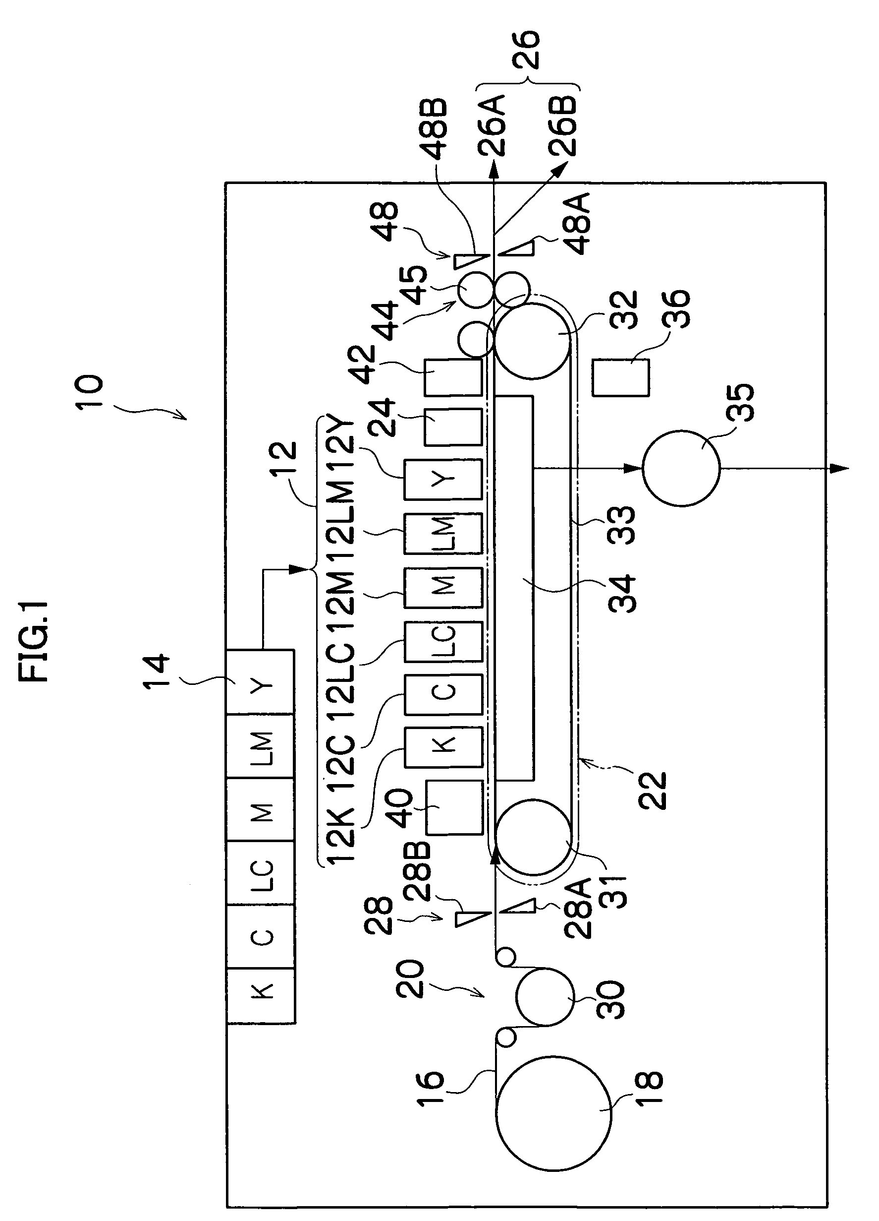
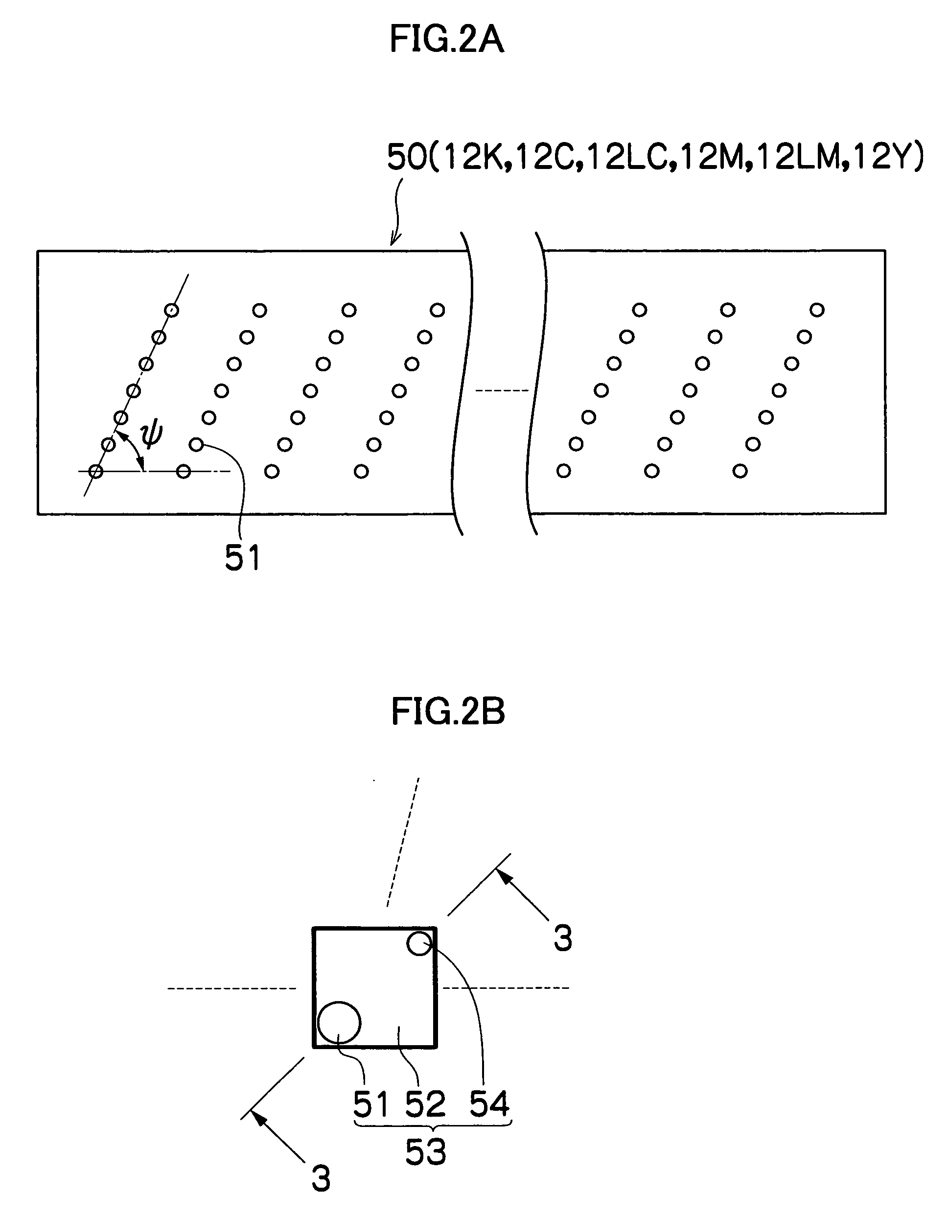
[0074]FIG. 1 is a general schematic drawing of an inkjet recording apparatus according to an embodiment of the present invention. As shown in FIG. 1, the inkjet recording apparatus 10 comprises: a printing unit 12 having a plurality of print heads 12K, 12C, 12LC, 12M, 12LM, and 12Y for ink colors of black (K), cyan (C), light cyan (LC), magenta (M), light magenta (LM) and yellow (Y), respectively; an ink storing / loading unit 14 for storing inks to be supplied to the print heads 12K, 12C, 12LC, 12M, 12LM, and 12Y; a paper supply unit 18 for supplying recording paper 16; a decurling unit 20 for removing curl in the recording paper 16; a suction belt conveyance unit (corresponding to the conveyance device) 22 disposed facing the nozzle face (ink-droplet ejection face) of the print unit 12, for conveying the recording paper 16 while keeping the recording paper 16 flat; a print determination unit 24 for reading the printed result pr...


PUM


Abstract

The liquid droplet ejection apparatus comprises: a plurality of ejection heads having an ejection surface in which nozzles for ejecting droplets of liquid towards an ejection receiving medium are arranged two-dimensionally; a conveying device which conveys at least one of the ejection heads and the ejection receiving medium in a fixed direction to cause relative movement of the ejection heads and the ejection receiving medium in a relative movement direction; and a droplet ejection control device which performs droplet ejection control whereby droplets of the liquid are ejected from the ejection heads towards the ejection receiving medium together with the relative movement caused by the conveying device, and a row of dots is formed by the droplets of the liquid landing on the ejection receiving medium in which at least some of the dots overlap in a main scanning direction substantially perpendicular to the relative movement direction, wherein when a position between nozzles at which a droplet ejection time difference between adjacent dots in the main scanning direction in one ejection head differs from a droplet ejection time difference between other adjacent dots is referred to as a specific time difference nozzle pair position in a corresponding ejection head, the ejection head is positioned so that the specific time difference nozzle pair position differs in the main scanning direction between at least two of the ejection heads.

Description

BACKGROUND OF THE INVENTION [0001] 1. Field of the Invention [0002] The present invention relates to a liquid droplet ejection apparatus and an image forming apparatus, and more particularly to a structure of a liquid droplet ejection apparatus that uses an ejection head in which numerous liquid droplet ejection ports (nozzles) are arranged two-dimensionally in high density, and to an image forming apparatus which forms an image on a recording medium using liquid droplets ejected from the liquid droplet ejection apparatus. [0003] 2. Description of the Related Art [0004] An inkjet recording apparatus causes ink droplets to be ejected onto a recording medium by ejecting ink from a recording head in accordance with a printing signal while causing recording paper or another recording medium to move relative to the recording head (ejection head) provided with nozzles for ink ejection, thereby forming an image using these ink dots. [0005] Increased nozzle density is desired for enabling p...

Claims


Application Information

Patent Timeline
Patent Type & Authority Applications(United States)
IPC IPC(8): B41J2/145B41J29/38
CPCB41J2/145
Inventor TATSUMI, SETSUJI
Owner FUJIFILM CORP
Why Eureka
Try Eureka