Grass collecting apparatus for lawn mower

a technology for collecting apparatus and lawn mowers, which is applied in the field of lawn mowers, can solve the problems of easy damage to elastic members, easy breakage (chipped) and achieves the effects of easy damage through strong frictional contact, easy breakage or damage, and short time period

Active Publication Date: 2005-10-06
KUBOTA LTD
View PDF8 Cites 4 Cited by
  • Summary
  • Abstract
  • Description
  • Claims
  • Application Information

AI Technical Summary

Benefits of technology

[0009] With the above-described construction, during a grass collecting operation when the guide hood is kept closed and also under a condition when the guide hood is opened, the free end of the movable sealing plate approaches the fixed sealing plate, thereby to close any gap formed between the grass collecting container support and the guide hood, thus preventing accidental drop of mowed grass or the like through such gap. Incidentally, a conventional standard solution for closing such gap is using an elastic sealing member made of rubber or the like. However, after being used for an extended period of time, such elastic sealing member tends to harden or embrittle, thus being easily broken (chipped) or damaged. Further, such elastic member can be easily damaged through strong frictional contact by hard grass or the like. Hence, such member will need to be replaced in a relatively short period of time. On the other hand, according to one preferred embodiment of the present invention, the fixed sealing plate and the movable sealing plate comprise metal plates. With this, replacement thereof becomes unneeded substantially, thus providing an advantage in maintenance.
[0010] In order to allow the fixed sealing plate to fully exhibit its original sealing function as well as its further function of preventing inadvertent displacement of the grass collectin...

Problems solved by technology

However, after being used for an extended period of time, such elastic sealing member tends to harden or embrittle, thus being easily...

Method used


Image

  • Grass collecting apparatus for lawn mower
  • Grass collecting apparatus for lawn mower
  • Grass collecting apparatus for lawn mower

Examples


Embodiment Construction

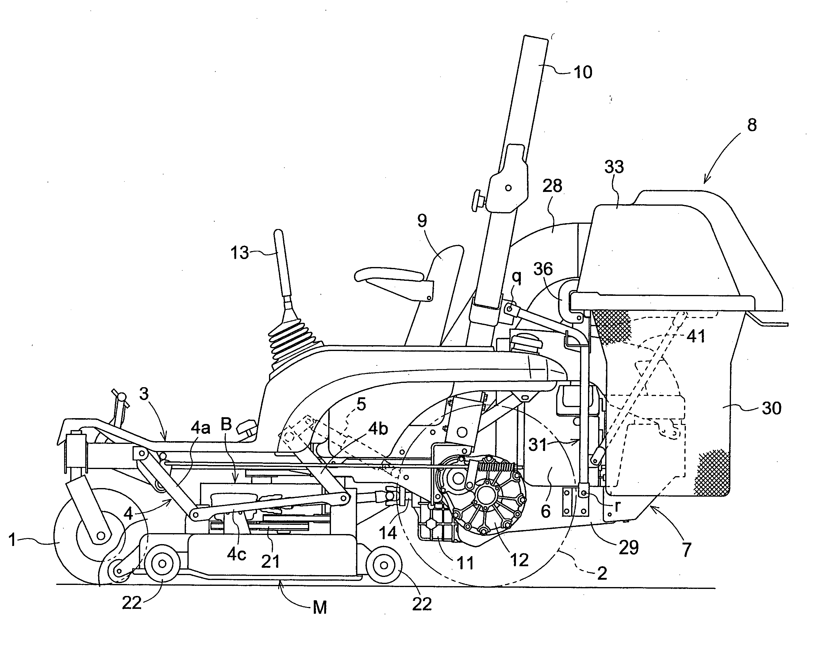
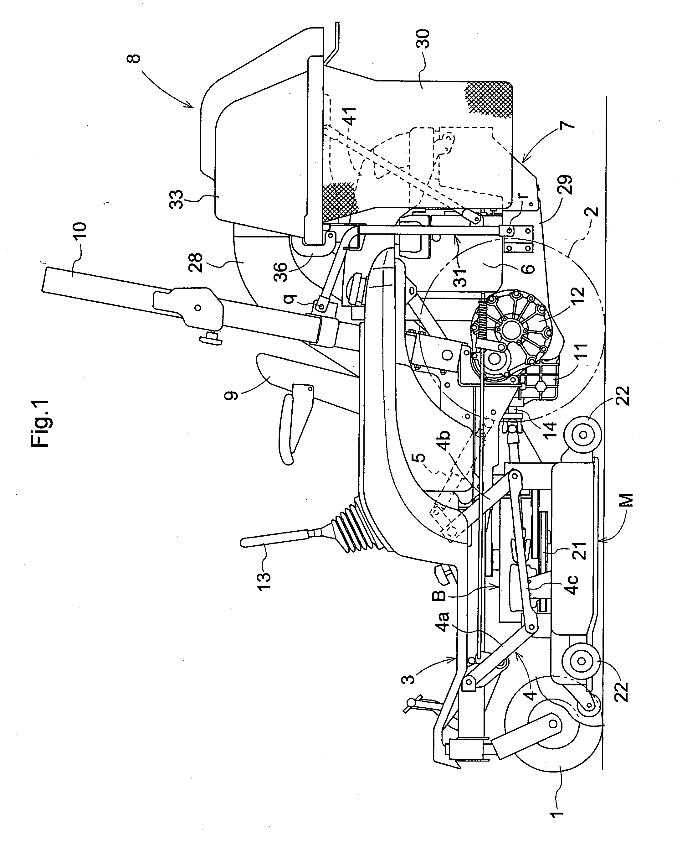
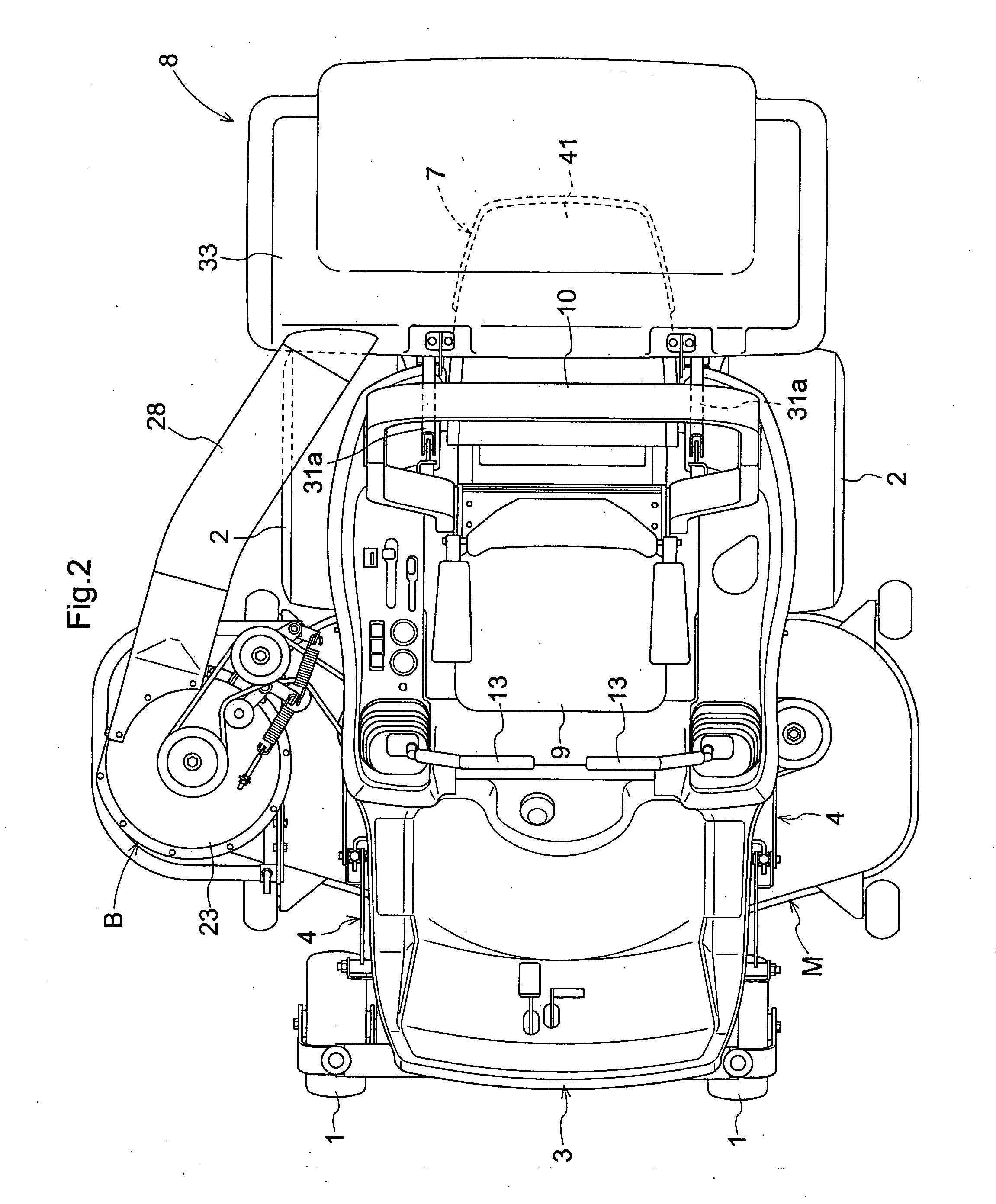
[0027]FIG. 1 shows an overall side view of a lawn mower relating to the present invention. FIG. 2 is a plan view of the same. In this lawn mower, a traveling vehicle body 3 mounts a pair of right and left front wheels 1 configured as caster wheels and a pair of right and left driving rear wheels 2. To the bottom of this traveling vehicle body 3, there is suspended a mower unit M to be liftable up / down via a pair of right and left quadruple link mechanisms 4 each consisting of a front link 4a, a rear link 4b and lower connecting links 4c. By lifting up / down the link mechanisms 4 by a hydraulic cylinder 5, the mower unit M can be lifted up / down substantially in parallel. On the rear side of the traveling vehicle body 3, there is mounted an engine section 7 housing an engine 6, the section 7 projecting rearward from the rear wheels 2 and also a grass collecting apparatus 8 for collecting mowed grass, lawn or the like is mounted across and over the engine section 7. A driver's seat 9 is...


PUM


Abstract

A grass collecting apparatus includes a grass collecting container support; at least one grass collecting container mounted on the container support and having an upper end opening edge for receiving mowed grass or the like through a conduit, a guide hood for covering the grass collecting container from the above, a support portion for supporting the guide hood while allowing its displacement from a closed position to an opened position; a fixed sealing plate provided to the grass collecting container support in the vicinity of the support portion; and a movable sealing plate provided to the guide hood in the vicinity of the support portion. The movable sealing plate is disposed in opposition to the fixed sealing plate, and a free end of the movable sealing plate displaceable in association with opening/closing displacement of the guide hood approaches the fixed sealing plate at least when the guide hood is at the closed position or the opened position.

Description

BACKGROUND OF THE INVENTION [0001] 1. Field of the Invention [0002] This invention relates to a grass collecting apparatus for a lawn mower, the apparatus being connected to a rear portion of a traveling vehicle body which travels with a mower unit being mounted thereto. [0003] 2. Description of the Related Art [0004] A grass collecting apparatus of the above type is known from U.S. Pat. No. 4,723,398 or U.S. Pat. No. 6,226,970, in either of which an upper opening edge of a bag-like grass collecting container having an upper opening is attached and supported to a grass colleting container support disposed erect from the vehicle body and a guide hood covering this grass collecting container from the above is connected to a mowed grass discharge conduit extending from a mower implement. [0005] In the case of the grass collecting apparatus with the above-described construction, the grass collecting container is detached by pivotally opening the guide hood upward, during which, however,...

Claims


Application Information

Patent Timeline
IPC IPC(8): A01D34/64A01D43/00A01D34/63A01D43/063
CPCA01D43/063
Inventor SAMEJIMA, KAZUOTOGOSHI, YOSHIKAZUASAHARA, MASATOSHIMADA, HIROSHI
Owner KUBOTA LTD
Why Eureka
Try Eureka