


Quick Research
Generate reliable direction feasibility study reports for your R&D in just a few steps.

Technical Q&A
Discover and master advanced knowledge NOW. Basics, ideas, possibilities, all at once.

Find Solutions
As an expert in R&D theories, this can generate solutions to your technical problems instantly.

Evaluate Feasibility
Analyze your overall solution with one click, know your potential R&D risks in advance.

Monitor Landscape
Get weekly tech updates, stay abreast of the latest tech innovations and key insights.
PLL circuit and radio communication terminal apparatus using the same
a technology of radio communication terminal and circuit, which is applied in the direction of digital transmission, pulse automatic control, transmission, etc., can solve the problems of increasing the number of components mounted outside, increasing the mounting area, and increasing the number of terminals, so as to reduce the number of lpfs, simplify the design of the pll circuit, and reduce the mounting area and the number of pins
- Summary
- Abstract
- Description
- Claims
- Application Information
AI Technical Summary
Benefits of technology
Problems solved by technology
Method used
Image

Examples
embodiment 1
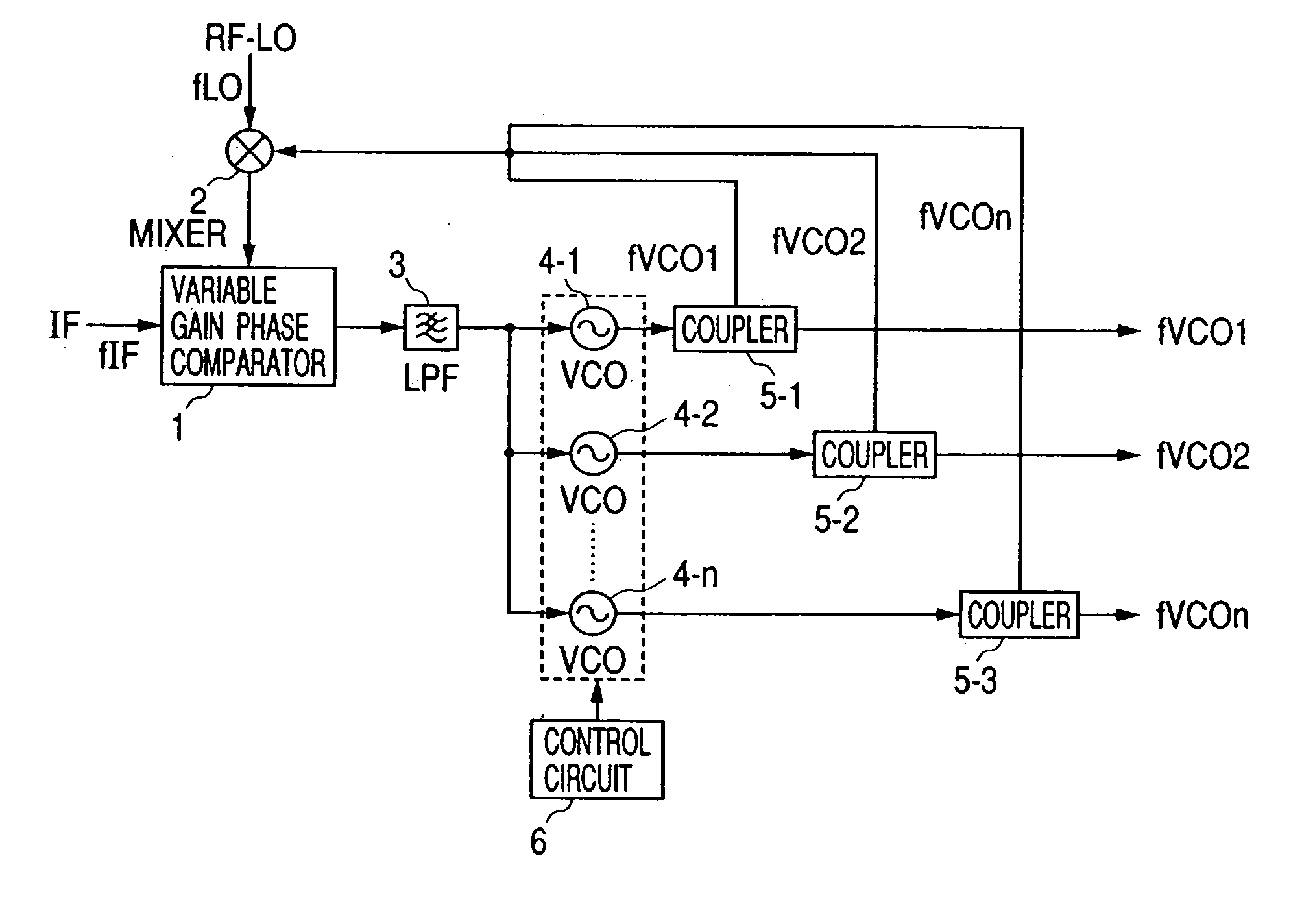
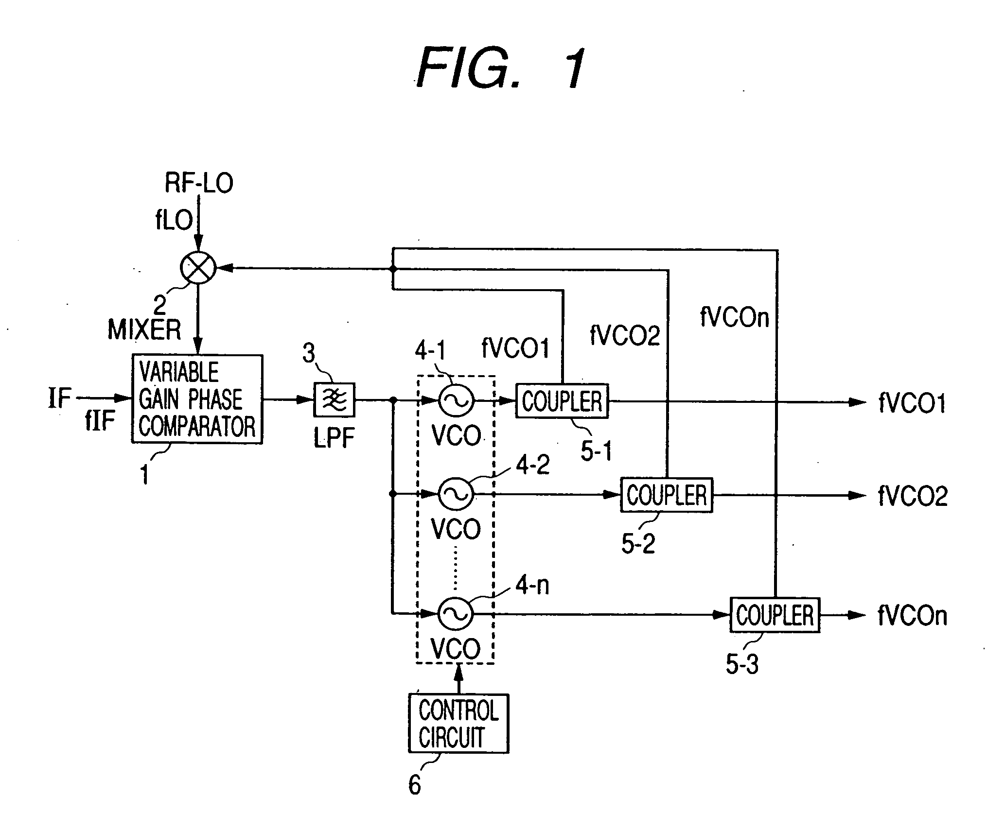
[0031]FIG. 1 is a view showing a configuration of PLL circuit according to a first embodiment of the present invention.
[0032] The PLL circuit of the present invention comprises a variable-gain phase comparator 1, a mixer 2, an LPF 3, n pieces of VCOs 4-1 to 4n, n pieces of couplers 5-1 to 5-n, and a control circuit 6 for controlling the on / off of the operation of the VCOs.
[0033] Two signals are inputted to the variable-gain phase comparator 1. A first input signal is a reference signal IF having a frequency of fIF, and a second input signal is an output signal from the mixer 2. The variable-gain phase comparator 1 compares the reference signal IF with the output signal from the mixer 2 so as to output a signal proportional to a phase difference between these signals. Then, the output signal from the variable-gain phase comparator 1 is inputted to the VCOs 4-1 to 4n after an unnecessary noise is eliminated by the LPF 3. Each output signal of the VCOs 4-1 to 4-n is inputted to one o...
embodiment 2
[0044] Next, the following is a description on a PLL circuit according to a second embodiment of the present invention.
[0045]FIG. 4 is a view showing a configuration of the PLL circuit according to the second embodiment of the present invention.
[0046] The PLL circuit of this second embodiment is constructed as a circuit having the following features. More specifically, a phase comparator 11 varying a gain by input amplitude is used in place of the variable-gain phase comparator 1 used in the first embodiment, and further, a variable gain amplifier 12 is interposed between the mixer 2 and the phase comparator 11. The gain of the variable gain amplifier 12 is controlled in accordance with the sensitivity of the VCOs 4-1 to 4-n, and the input amplitude to the phase comparator 11 is varied so as to change a gain of the phase comparator 11, and thereby, a loop band of the PLL circuit can be optimized.
[0047]FIG. 5 is a view showing a configuration of the phase comparator 11.
[0048] The...
embodiment 3
[0053] Next, the following is a description on a PLL circuit according to a third embodiment of the present invention.
[0054]FIG. 6 is a view showing a configuration of the PLL circuit according to the third embodiment of the present invention.
[0055] The PLL circuit of this third embodiment is a circuit having the following features. More specifically, LPFs 16-1 to 16-m connected in parallel are interposed between the variable-gain phase comparator 1 and the mixer 2 used in the above first embodiment, and LPFs 15-1 to 15-m connected in parallel are connected to the first input of the variable-gain phase comparator 1. Further, a control circuit 14 for controlling the on-off of the VCOs 4-1 to 4-n, LPFs 15-1 to 15-m, and LPFs 16-1 to 16-m is used in place of the control circuit 6.
[0056] These LPFs 15-1 to 15-m and LPFs 16-1 to 16-m are used for eliminating a noise inputted to the variable-gain phase comparator 1. Moreover, the reference signal IF has m-way frequencies fIF. The contr...
PUM
 Abstract
Description
Claims
Application Information
 - R&D Engineer
- R&D Manager
- IP Professional
- Industry Leading Data Capabilities
- Powerful AI technology
- Patent DNA Extraction
Browse by: Latest US Patents, China's latest patents, Technical Efficacy Thesaurus, Application Domain, Technology Topic, Popular Technical Reports.
© 2024 PatSnap. All rights reserved.Legal|Privacy policy|Modern Slavery Act Transparency Statement|Sitemap|About US| Contact US: help@patsnap.com