Adapter panel, electronic equipment, and cable connector identification system
a technology of adapter panels and identification systems, applied in the direction of coupling device connections, instruments, optical elements, etc., can solve the problems of inaccuracy of measurement, electrical equipment where a plurality of plugs are inserted or removed such as a telephone switching device is subject to insertion errors, and low yield
- Summary
- Abstract
- Description
- Claims
- Application Information
AI Technical Summary
Benefits of technology
Problems solved by technology
Method used
Image
Examples
first embodiment
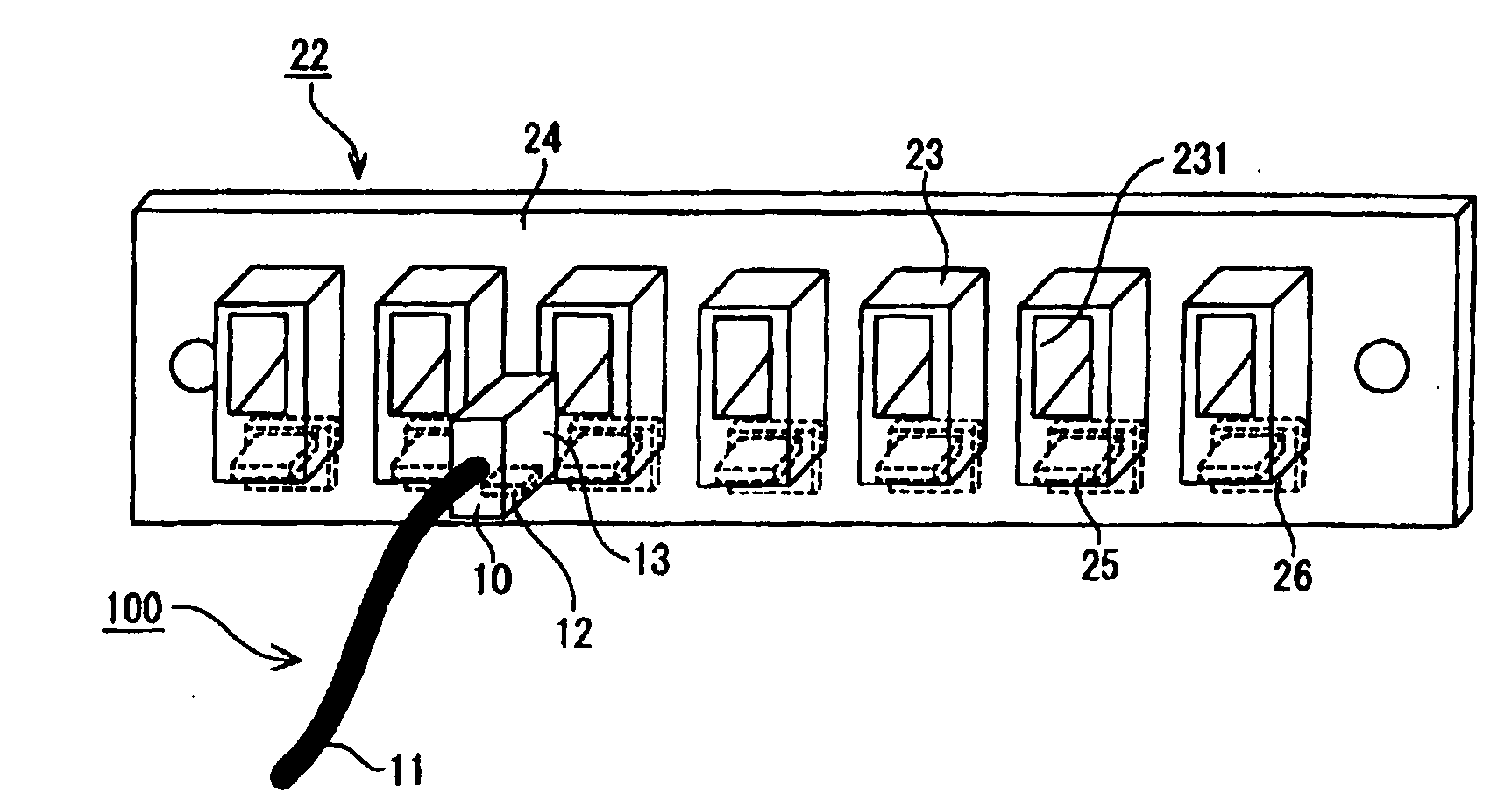
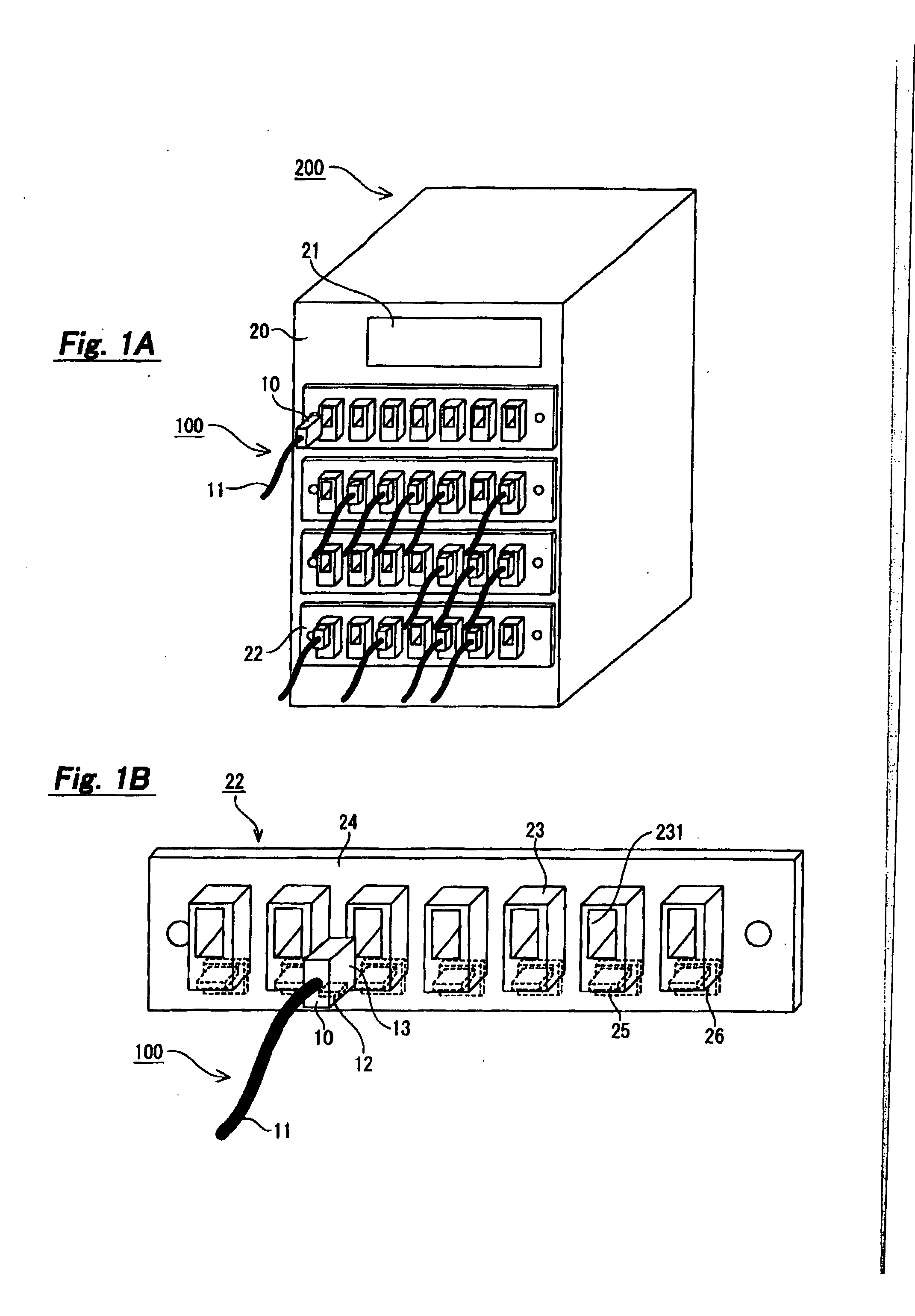
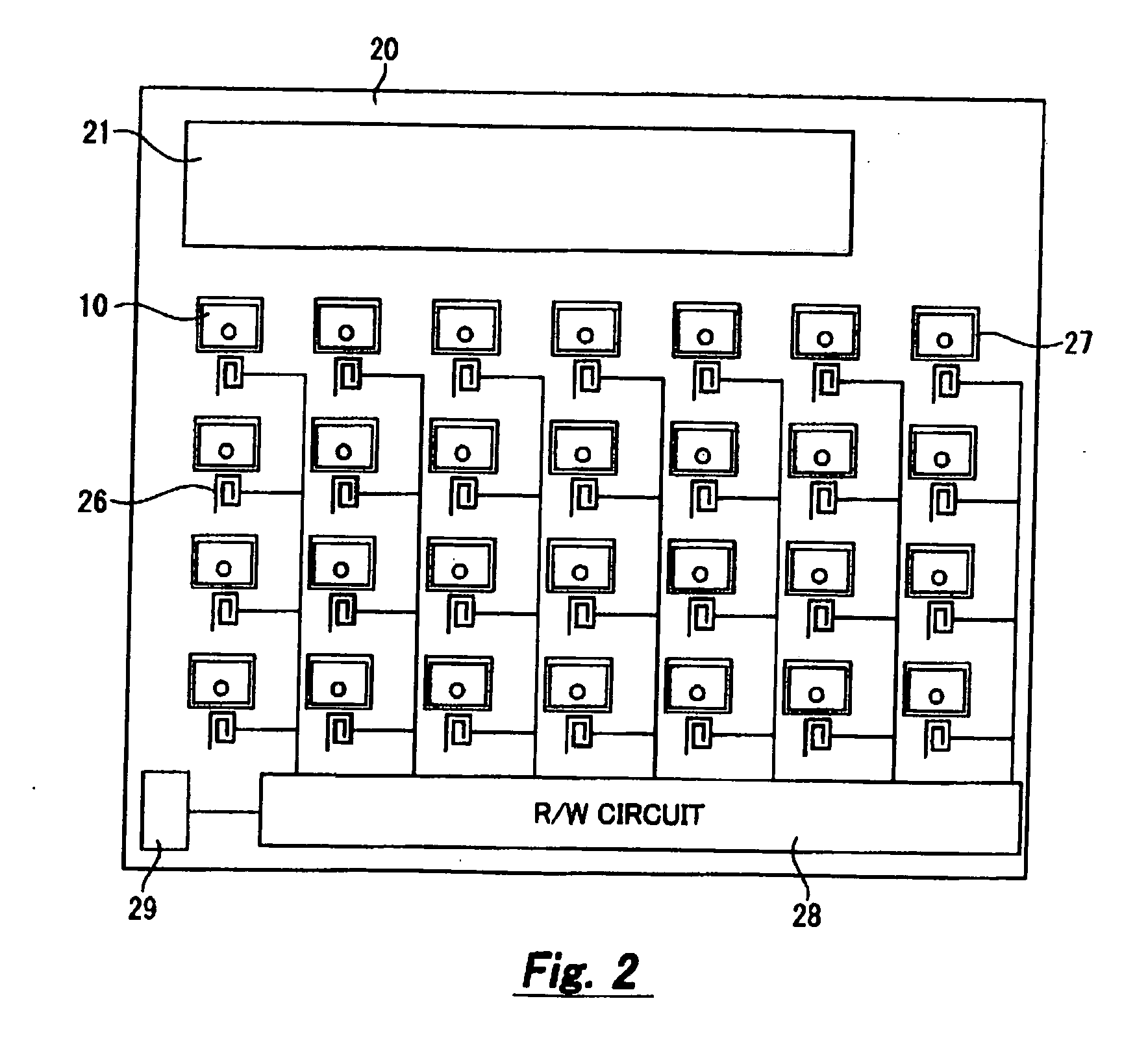
[0044] A first embodiment of the invention applies a cable connector identification system to a circuit switching device, which is also referred to hereinafter as a telephone switching device. The circuit switching device is unique in the specific structure. FIG. 1A illustrates the entire configuration of the cable connector identification system. The cable connector identification system is composed of an optical fiber cable 100 and a circuit switching device 200.
[0045] The optical fiber cable 100 has an optical fiber connector 10 and an optical fiber code 11. The optical fiber cable 100, the optical fiber connector 10, and the optical fiber code 11 are abbreviated hereinafter as the optical cable 100, the optical connector 10, and the optical code 11, respectively.
[0046] The optical connector 10 is a male plug made of insulating material such as plastic, synthetic resin, and rubber. The optical code 11 has an optical fiber inside, though not shown. The other end of the optical c...
second embodiment
[0072] A second embodiment of the invention applies the cable connector identification system to a telephone switching device, just like the first embodiment. FIG. 6 is a perspective view of a telephone switching device. The telephone switching device can be used by connecting an optical cable to the telephone switching device as in the first embodiment.
[0073] As shown in FIG. 6, one side surface of the telephone switching device 400 has a display section 41 and a plurality of adapter panels 42. A plurality of adapters 43 and booster antennas 44 are placed in each adapter panel 42. Further, a plurality of R / W antennas 45 are placed in the internal surface of the telephone switching device 400 where the adapter panels 42 are mounted.
[0074] A connector of a cable for telephone line connection, not shown, is inserted to each adapter 43 in the same way as the optical connector 10 and they are electrically connected inside the adapter 43. Further, the Coil-on-Chip RFID 12 is placed in ...
third embodiment
[0080] A third embodiment of the invention applies the cable connector identification system to a telephone switching device, just like the second embodiment. The configuration of the telephone switching device is the same as described in FIG. 6. The telephone switching device 400 of the third embodiment is unique in the internal processing just like the second embodiment.
[0081] The cable connector identification system of the third embodiment is used by connecting the optical cable 100 to the telephone switching device 400 as in the first embodiment. In the optical cable 100 connected to the switching device 400, the core alignment accuracy to align the optical axis is so important as to greatly affect the communication performance. However, it is inevitable that the core alignment accuracy deteriorates by repeating the insertion and removal of the optical cable 100 into and from the telephone switching device 400. Thus, it is necessary to replace the optical cable 100 every after...
PUM
 Abstract
Description
Claims
Application Information
 - R&D
- Intellectual Property
- Life Sciences
- Materials
- Tech Scout
- Unparalleled Data Quality
- Higher Quality Content
- 60% Fewer Hallucinations
Browse by: Latest US Patents, China's latest patents, Technical Efficacy Thesaurus, Application Domain, Technology Topic, Popular Technical Reports.
© 2025 PatSnap. All rights reserved.Legal|Privacy policy|Modern Slavery Act Transparency Statement|Sitemap|About US| Contact US: help@patsnap.com


