Data distribution device and transmission method
a data distribution and transmission method technology, applied in data switching networks, selective content distribution, data transmission services, etc., can solve problems such as data transmission delay and interruption of received images, and achieve the effect of preventing frequent handover processing or sudden interruption of communication and efficient data communication
- Summary
- Abstract
- Description
- Claims
- Application Information
AI Technical Summary
Benefits of technology
Problems solved by technology
Method used
Image

Examples
embodiment 1
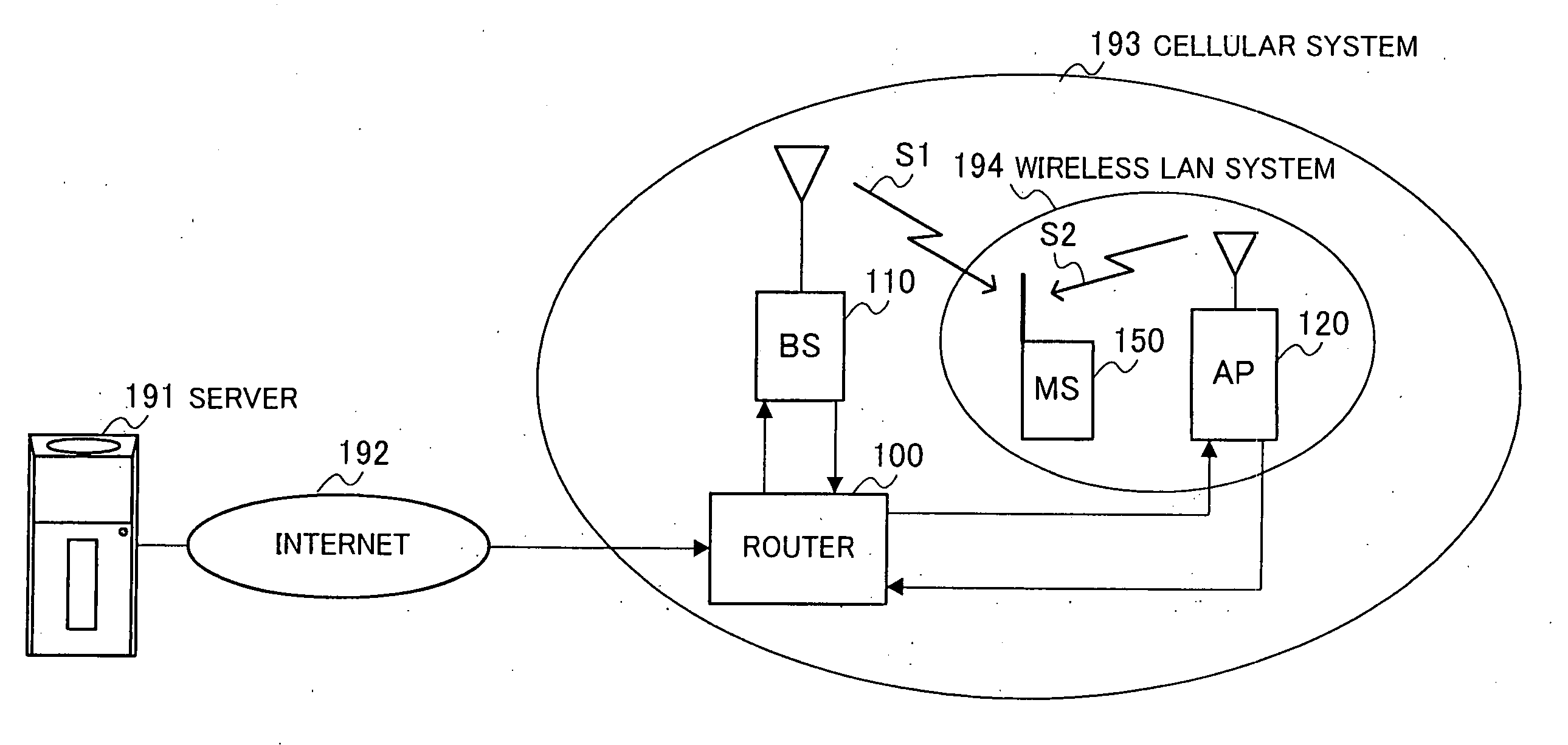
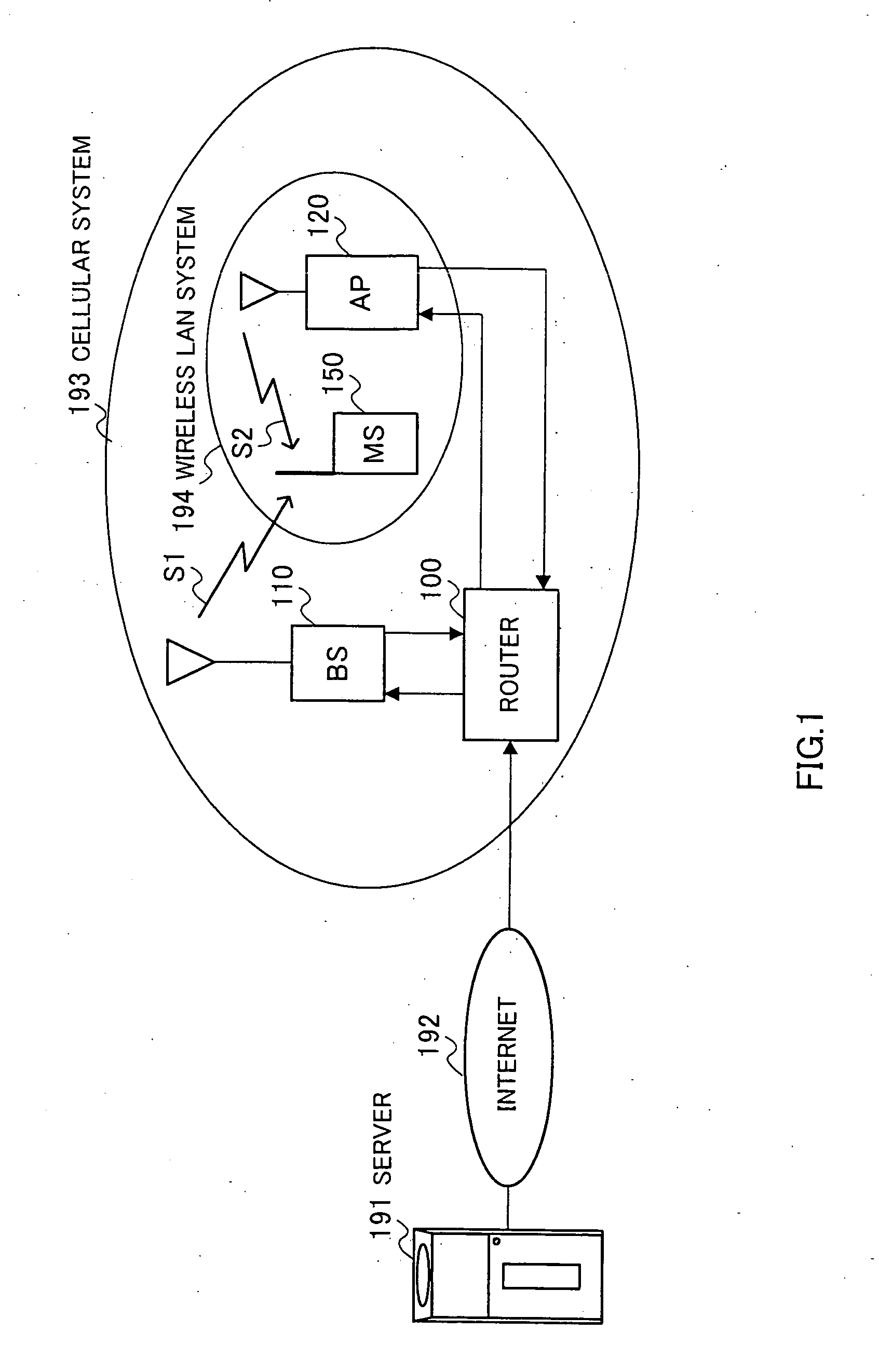
[0031]FIG. 1 illustrates an overview of a wireless communication system according to Embodiment 1 of the present invention. Here, a case where image information sent from a server is sent to a mobile station apparatus (communication terminal apparatus) will be explained as an example.
[0032] A wireless communication system shown in FIG. 1 includes a server 191, Internet 192, a cellular system 193 and a wireless LAN system 194. The cellular system 193 includes a router 100 and a base station apparatus (BS) 110 and the wireless LAN system 194 includes an access point apparatus (AP) 120. The area of the wireless LAN system 194 exists within the area of the cellular system 193. The cellular system 193 and the wireless LAN system 194 are communication systems independent of each other.
[0033] The server 191 sends image information to the router 100 through the Internet 192. This image information consists of basic data which has low resolution but can configure one image (screen) by itse...
embodiment 2
[0061]FIG. 5 is a block diagram showing a configuration of a mobile station apparatus according to Embodiment 2 of the present invention. This mobile station apparatus has a basic configuration similar to that of the mobile station apparatus shown in FIG. 3, and therefore the same components are assigned the same reference numerals and explanations thereof will be omitted.
[0062] A feature of the mobile station apparatus shown in FIG. 5 is that it is provided with an error decision section 251 and an ACK / NACK signal generation section 252 and sends a retransmission request to the transmitting side when there is an error in received data.
[0063] The error decision section 251 decides the presence / absence of an error in the data output from a data acquisition section 154 and outputs the decision result to the ACK / NACK signal generation section 252. The ACK / NACK signal generation section 252 generates an ACK signal or NACK signal based on this decision result and sends this signal to a...
embodiment 3
[0070] A wireless communication system according to Embodiment 3 of the present invention has a configuration similar to that of the wireless communication system shown in FIG. 1, and therefore a block diagram only showing a configuration of a router will be shown in FIG. 8 here.
[0071] A router 100a is provided with an allocation section 301, an allocation ratio calculation section 302, a wireless LAN transmittable rate information acquisition section 303 and a cellular transmittable rate information acquisition section 304.
[0072] The allocation section 301 receives (acquires) data sent from the server 191 through the Internet 192, allocates and outputs the data sent from the server 191 based on an allocation ratio output from the allocation ratio calculation section 302 to the respective systems. The allocation ratio calculation section 302 decides the allocation ratio based on a transmittable data rate of the wireless LAN system acquired through the wireless LAN transmittable ra...
PUM
 Abstract
Description
Claims
Application Information
 - R&D
- Intellectual Property
- Life Sciences
- Materials
- Tech Scout
- Unparalleled Data Quality
- Higher Quality Content
- 60% Fewer Hallucinations
Browse by: Latest US Patents, China's latest patents, Technical Efficacy Thesaurus, Application Domain, Technology Topic, Popular Technical Reports.
© 2025 PatSnap. All rights reserved.Legal|Privacy policy|Modern Slavery Act Transparency Statement|Sitemap|About US| Contact US: help@patsnap.com