
Multilayer film reflector for soft X-rays and manufacturing method thereof

Inactive Publication Date: 2005-09-29
CANON KK
View PDF6 Cites 22 Cited by
  • Summary
  • Abstract
  • Description
  • Claims
  • Application Information

AI Technical Summary

Benefits of technology

[0016] It is, therefore, an object of the present invention to provide a multilayer film reflector having good reflection characteristics also in a soft X-ray region, by promoting crystallization of a low refractive index layer to decrease the refractive index thereof, thereby increasing the difference in refractive index between the low refractive index layer and a high refractive index layer.

Problems solved by technology

That is, a light hardly refracts in the soft X-ray region so hardly that a dioptric system utilizing refraction cannot be theoretically used.
However, when a reflector having a single layer film formed therein is used as the catoptric system, if an incidence angle of a soft X-ray incident on the reflector is small, the reflectance of the reflector becomes extremely low.
Specifically, when the reflector is used for an incidence angle of 70° or less, the reflectance for the soft X-rays is so low that the reflector cannot be used.

Method used


Image

  • Multilayer film reflector for soft X-rays and manufacturing method thereof
  • Multilayer film reflector for soft X-rays and manufacturing method thereof
  • Multilayer film reflector for soft X-rays and manufacturing method thereof

Examples


example 1

[0028] At first, the configuration of a multilayer film reflector of Example 1 will be described with reference to a sectional view shown in FIG. 1. In FIG. 1, reference numeral 1 denotes a substrate made of Ni. On the substrate 1, a high refractive index layer 4 made of Si (having a refractive index nB of 0.999 in a crystalline state and a thickness of 5 nm), an intermediate layer 3 made of Zn (having a thickness of 1 nm), and a low refractive index layer 5 made of Mo (having the refractive index nA of 0.921 in a crystalline state and the thickness of 4 nm) are stacked. A multilayer film 2 is formed by repeatedly stacking 60 layers in total of the high refractive index layer 4, the intermediate layer 3 and the low refractive index layer 5 in the mentioned order from the substrate 1 side. However, in FIG. 1, the multilayer film 2 is shown as being formed of 15 layers for convenience of the description. In FIG. 1, the thicknesses and number of the refractive index layers are designed...

example 2

[0036] The configuration of a multilayer film reflector of Example 2 will be now described with reference to a sectional view of FIG. 3. In FIG. 3, in contrast to FIG. 1, an intermediate layer is formed in each of interfaces between high refractive index layers and low refractive index layers.

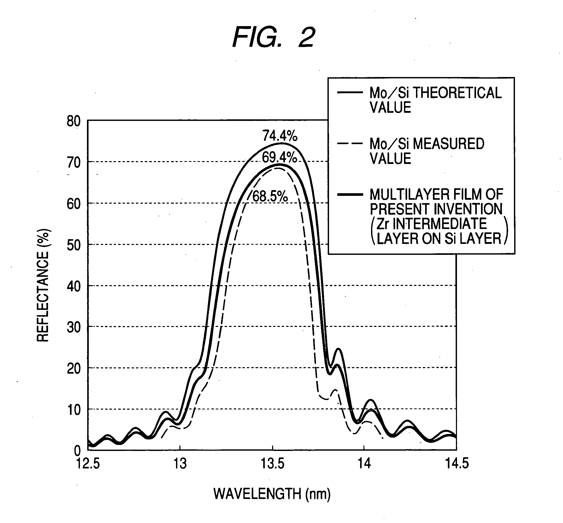
[0037] In FIG. 3, reference numeral 11 denotes a substrate made of Cu. On the substrate 11, high refractive index layers 14 made of Si (having a refractive index nA of 0.999 in a crystalline state and a thickness of about 4.5 nm), intermediate layers 13 made of Zr (having a thickness of about 1 nm), and low refractive index layers 15 made of Mo (having a refractive index nA of 0.921 in a crystalline state and a thickness of about 4 nm) are stacked. A multilayer film 12 is formed by repeatedly stacking 50 layers in total of a high refractive index layer 14, an intermediate layer 13, a low refractive index layer 15, and an intermediate layer 13 in the mentioned order from the substrate 11 side. ...


PUM


Abstract

A multilayer film reflector for X-rays has alternately stacked layers formed on a substrate and comprising a layer (high refractive index layer) comprising a material having a large difference between a refractive index to soft X-ray and a refractive index in vacuum, and a layer (low refractive index layer) comprising a material having a small difference between a refractive index to soft X-ray and a refractive index in vacuum, wherein at least one intermediate layer having a crystalline structure is provided between the low refractive index layer and the high refractive index layer. Thereby, the crystallization of the low refractive index layer is promoted, the refractive index of the low refractive index layer is lowered, so that the reflectance of the multilayer film reflector is improved.

Description

BACKGROUND OF THE INVENTION [0001] 1. Field of the Invention [0002] The present invention relates to a multilayer film reflector and a manufacturing method thereof, and particularly to a multilayer film reflector having good reflection characteristics in a soft X-ray region of a wavelength of about 1 to 30 nm, and the manufacturing method thereof. The multilayer film reflector in accordance with the present invention is used in various X-ray optical systems. For instance, it can be used in X-ray lithography, an X-ray telescope and an exposure device. [0003] 2. Description of the Related Art [0004] In general, a complex index of refraction for a material is expressed by the equation n=1−δ−ik (wherein n is complex index of refraction; δ and k are real numbers; and k represents absorption of X-ray). The values of δ and k in the equation are much smaller than 1 in a soft X-ray region (wavelength: 1 to 30 nm), so that the complex index of refraction becomes a value extremely close to 1. ...

Claims


Application Information

Patent Timeline
IPC IPC(8): G02B5/08G02B5/20G21K1/06H01L21/027
CPCB82Y10/00G21K2201/067G21K1/062G02B5/0808
Inventor IMAI, KYOKOANDO, KENJIKANAZAWA, HIDEHIROTERANISHI, KOJIMIURA, TAKAYUKITAKATA, KAZUE
Owner CANON KK
Learn More