
Method and apparatus of cornea examination

a corneal and apparatus technology, applied in the field of corneal examination, can solve the problems of affecting the quality of the diffused light method, affecting the accuracy of the evaluator, so as to achieve the effect of increasing the ability of the evaluator and greater accuracy

Inactive Publication Date: 2005-09-29
ABDULLAYEV ERKIN +1
View PDF6 Cites 11 Cited by
  • Summary
  • Abstract
  • Description
  • Claims
  • Application Information

AI Technical Summary

Benefits of technology

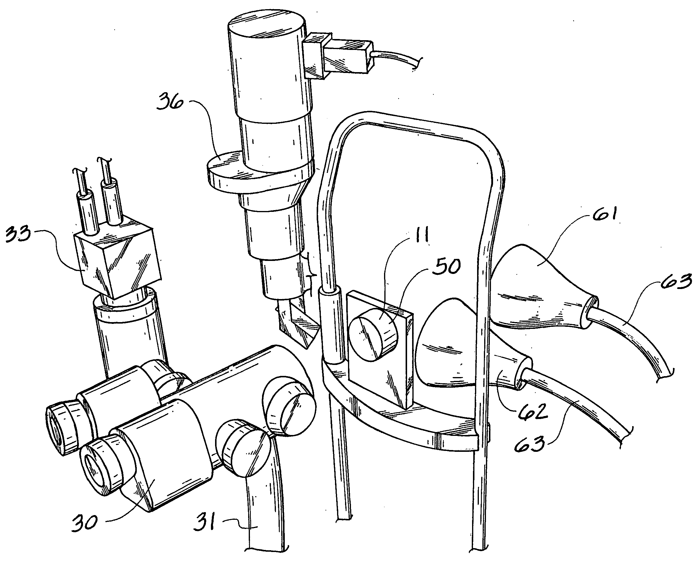
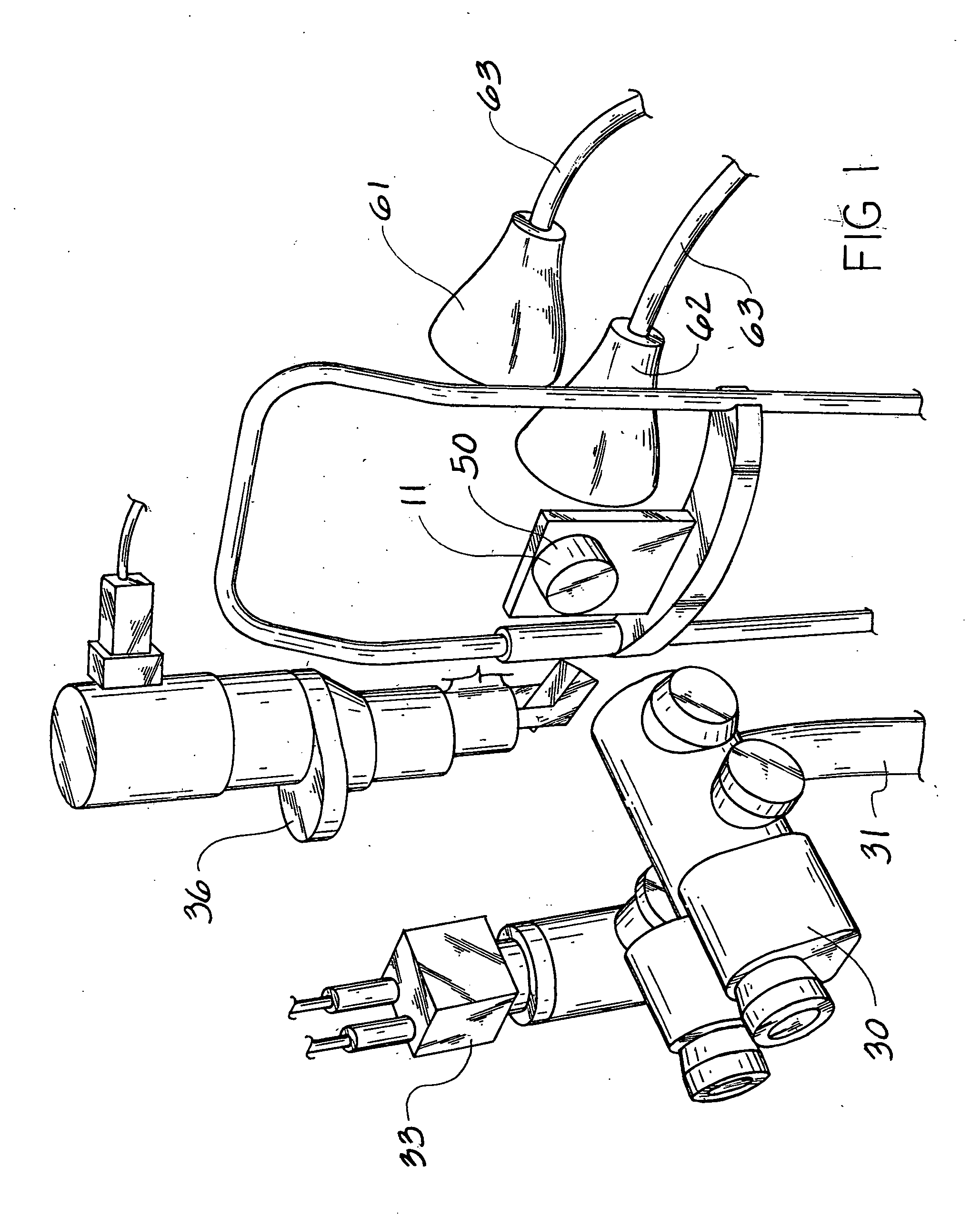
"This patent describes a method and apparatus for examining corneas that have been removed from a host and are intended for transplant. The corneas are placed in storage containers that protect them and position them for examination. The method involves using diffused light sources behind the cornea, with each light source impacting the cornea at a different angle. This allows for improved examination techniques using a slit lamp, while also minimizing the impact of direct light on the observer. The method also allows for the observation of cornea imperfections using virtually only the light that has been reflected from the imperfections. The apparatus used for this method is commonly available and can be modified for digital photography and videography. The data acquired through these means can be cataloged and shown at a later time, increasing the ability of the evaluator to accurately determine imperfections in the cornea and provide information to others regarding the status of the imperfections."

Problems solved by technology

If a slit lamp is used in conjunction, this method also allows improved examination techniques of the slit lamp examination, but often detracts from the diffused light method quality.
As both light rays move through the cornea, they encounter distortions as a result of scar tissue, or other types of undesirable features within or on the surface of the cornea.
While there is some minor reflection of light from the normal areas of the cornea, this is at an extremely low level.

Method used


Image

  • Method and apparatus of cornea examination
  • Method and apparatus of cornea examination
  • Method and apparatus of cornea examination

Examples


Embodiment Construction

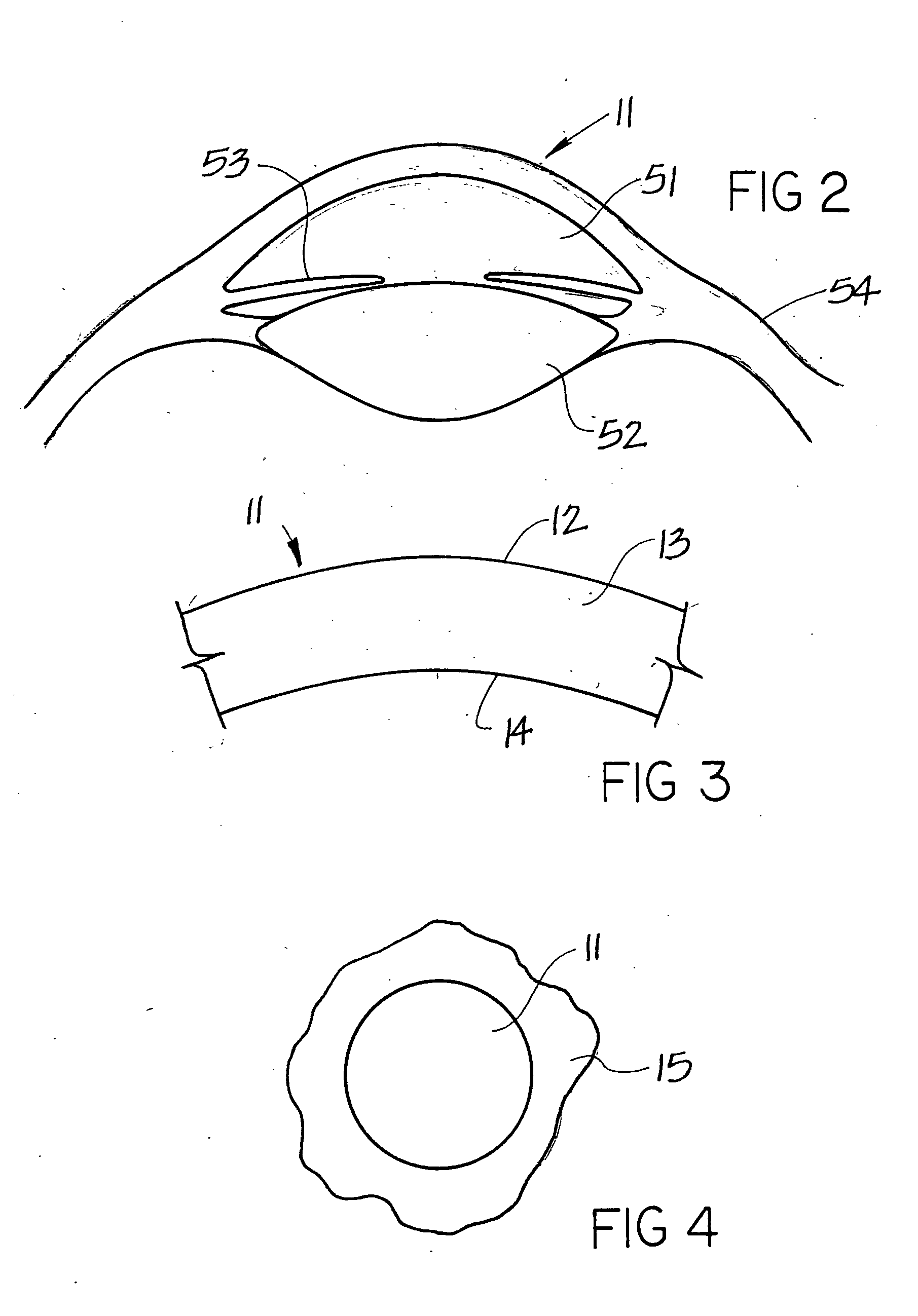
[0041] Referring now to FIG. 2, the cornea 11 is the transparent part of the external tunic of the eyeball. It is almost circular in shape, and may be slightly broader in the transverse band in the vertical direction. It is convex anteriorly, and projects forward from the sclerotic. The cornea 11 lies on top of an interior chamber 51, and in front of the lens 52 which is covered in part by the iris 53. The sciera 54 surrounds the peripheral edge of the cornea 11. The degree of curvature for each cornea 11 varies from individual to individual, as well as varies within the same individual during different stages of the life span. For example, a cornea 11 will tend to flatten out over time, so that an older person will exhibit a flatter cornea 11 than a younger person typically would.

[0042] Referring now to FIG. 3 The cornea 11 is comprised of multiple layers. Although each layer is technically separated by a membrane, where the membranes may be considered layers themselves, only the ...


PUM

PropertyMeasurementUnit
distanceaaaaaaaaaa
anglesaaaaaaaaaa
angleaaaaaaaaaa

Abstract

This invention comprises an improvement on the examination and evaluation of donor corneas. The improved apparatus includes the incorporation of a diffused light source, or sources, which are placed posteriorly to a donor cornea, with a viewing means placed anteriorly to said cornea. The apparatus involves the addition of the diffused light sources to existing apparatus, as well as the possible incorporation of a digital video camera or other electronic viewing means, which was not usable under the prior art. The method of placement of the diffused light source or sources is also novel, as compared with the prior art. Using this apparatus and method, the diffused light passes through the cornea, and is received by the viewing means. The viewing means is able to capture and image of the cornea, where the diffused light denotes any imperfections to the cornea. Use of the diffused light allows a complete view of the entire cornea at one time. The view of the cornea may be captured using a digital video camera or other means, with the image capable of being transmitted to another viewer, or where the entire examination can be done using a high resolution monitor.

Description

DISCLOSURE OF PRIOR ART [0001] Prior art dealing with corneal investigation has previously dealt primarily with the examination of intact corneas in living patients. The investigation of corneas that are from hosts, being post mortem procurements, have been reviewed using what is called a slit lamp, that shines a bright beam of light onto the front side of the cornea. [0002] Referring now to U.S. Pat. No. 4,187,005 (Rosenberger), a system for positioning a corneal endothelium microscope is shown. A flash system is discussed, but all light must originate in front of the eye. This system is intended for use with a living subject, and both the apparatus and the method are not suitable for determining corneal imperfections on subject corneas that are being examined for possible transplants. [0003] Referring now to U.S. Pat. No. 4,189,215 (Humphrey), a method for positioning a patient's eye is disclosed, where a positioning beam is used to move a patient's cornea to a optimal position fo...

Claims


Application Information

Patent Timeline
Patent Type & Authority Applications(United States)
IPC IPC(8): A61B3/00A61B3/10A61B3/14A61F2/14G01N21/95
CPCA61F2/141A61B3/107G01N21/95A61F2/142
Inventor ABDULLAYEV, ERKINBRYAN, G. SCOTT
Owner ABDULLAYEV ERKIN
Learn More