
Video communication systems and methods

a video communication system and video communication technology, applied in the field of multimedia communication, can solve the problems of preventing intranet users, unable to easily install video conferencing systems of parent applications, and unable to setup video conference across firewalls

Inactive Publication Date: 2005-09-22
CAMELOT TECH ASSOCS
View PDF12 Cites 35 Cited by
  • Summary
  • Abstract
  • Description
  • Claims
  • Application Information

AI Technical Summary

Benefits of technology

[0009] It is an object of the preferred embodiments of the inventions described in this application to provide a real-time video communications system with improved reliability, confidentiality, and connection capability.
[0010] It is a further object of the preferred embodiments of the inventions to provide a high quality video communications system that can be easily implemented over the Internet using the Transport Control Protocol (TCP) or Internet Protocol (IP) and can be easily installed as a high-end software system at a widely available user terminal, such as a personal computer.
[0013] It is another object of the preferred embodiments of the inventions to provide a method of video communications across a firewall without needing to alter the firewall or provide advanced functions in the firewall.
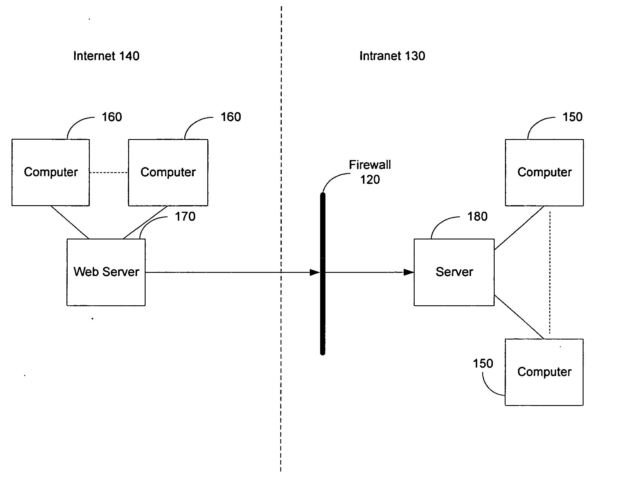
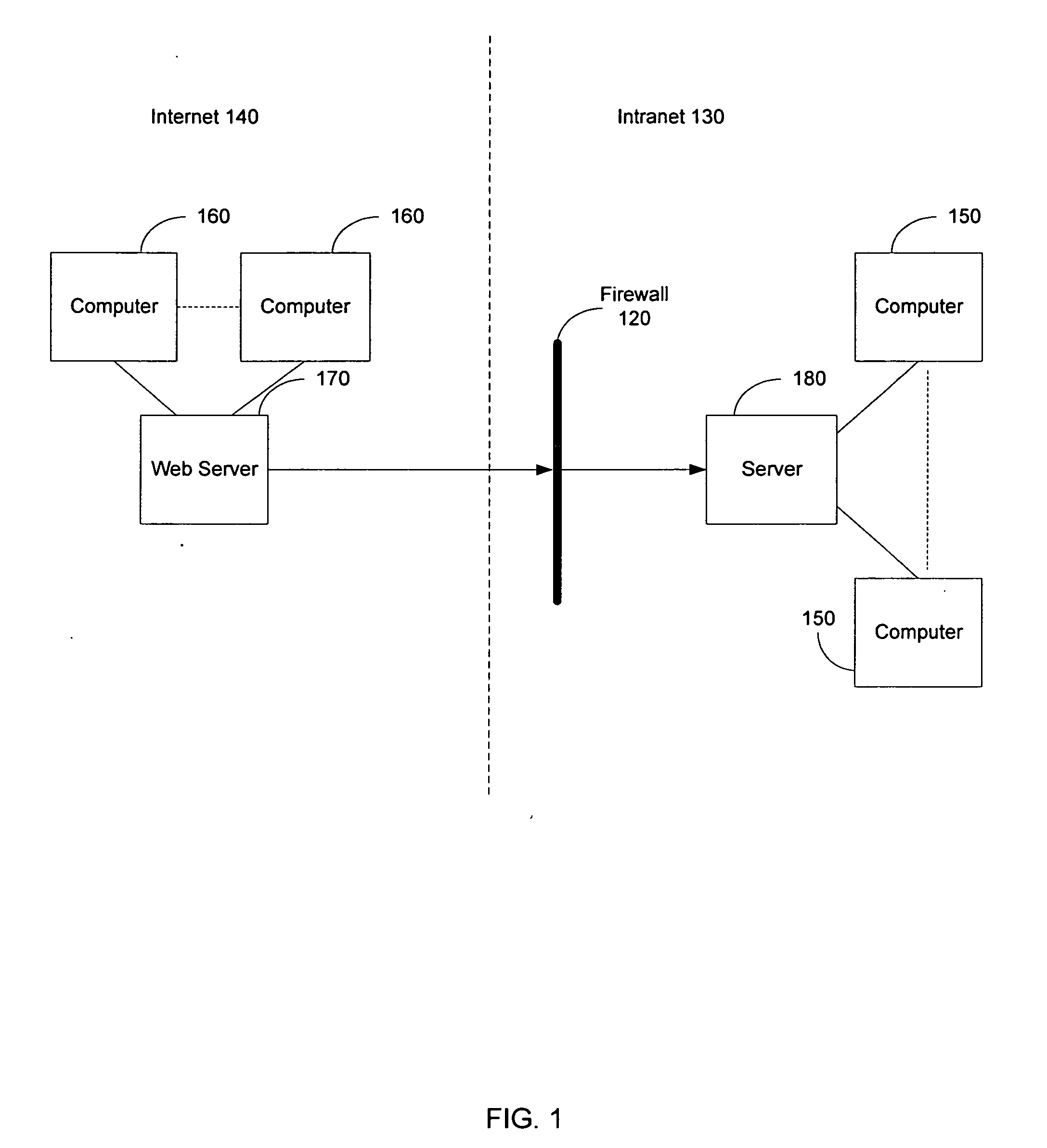
[0019] In another aspect of the inventions, a video communication system allows a video conference between multiple terminals located in different networks separated by firewalls. Before the video conference occurs, one terminal sends a list of all participating terminals and a conference start time to a terminal database. The terminal database stores the list of terminals and the start time. Also, the terminal database determines a proxy server that is to be utilized by all the terminals during the video conference. The terminal database and the proxy server are outside of the firewalls of the networks that contain the terminals. At the start time of the video conference, each of the terminals sends its registration information to the terminal database. In response, the terminal database sends the address of the proxy server to each terminal on the list of participating terminals. Next, each of the terminals establishes a persistent connection to the proxy server. The terminals then participate in the video conference via their respective persistent connections with the proxy server. The persistent connections with the proxy server allow for the exchange of audio / video data streams for the video conference between all the terminals without interference from firewalls.

Problems solved by technology

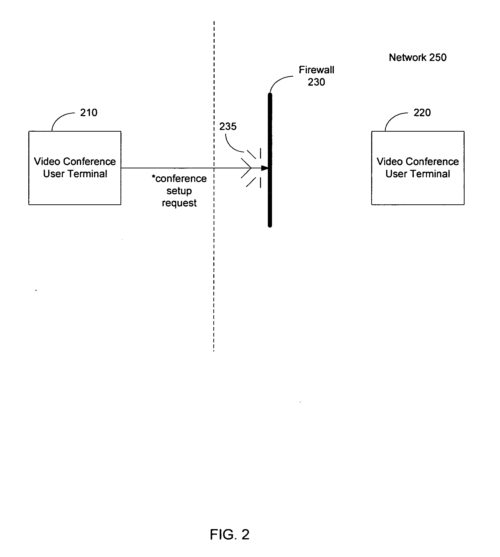
In another example, it is possible that a video conference cannot be setup across the firewall because the firewall is designed and configured to only work with very specific protocols that are not compatible with the protocols or other techniques used by the video conferencing system.
While the limitations and restrictions imposed by a firewall achieve the goal of enhancing security, they may prevent an Intranet user from using a video conferencing system with a user outside the Intranet.
Although the firewall configuration and settings may be altered by a network administrator when such a problem occurs, this frustrates the goal of the video conferencing systems of the parent applications to be easily installed and used without assistance.
While this may work for video conferencing systems using standardized protocols, such as the International Telecommunications Union's protocols H.323 and H.320, it will not work for improved video conferencing systems such as that in the parent applications that use improved, non-standard, protocols and compression techniques.

Method used


Image

  • Video communication systems and methods
  • Video communication systems and methods
  • Video communication systems and methods

Examples


Embodiment Construction

[0027] The preferred embodiments of the inventions are described with reference to exemplary video communications systems. However, the inventions are not limited to the preferred embodiments in their implementations. The inventions, or any aspect of the inventions, may be practiced in any video communications system. In addition, the preferred embodiments are shown in block diagram form and are described in this application without excessive detail in order to avoid obscuring the inventions, and in view of the fact that implementations of such systems are known to those of ordinary skill in the art and may be dependent upon circumstances surrounding the implementations. In other words, such specifics are variable but should be well within the purview of one skilled in the art. Where specific details are set forth in order to describe example embodiments of the inventions, it should be apparent to one skilled in the art that the invention can be practiced without, or with variation ...


PUM


Abstract

Video communications systems and methods video communications between user terminals in networks that are separated by a firewall. A first user terminal establishes a persistent connection with its proxy that is on the other side of a firewall protecting the terminal. Other terminals can conduct video calls or conferences with the first user terminal via the persistent connection. A terminal database server maintains information about each terminal, such as their addresses, and assists with establishing each video call or conference.

Description

CROSS-REFERENCE TO RELATED APPLICATIONS [0001] This application is a continuation-in-part application of U.S. patent application Ser. No. 10 / 755,067 filed on Jan. 9, 2004, and titled “Video Conferencing System”, and this application claims the benefit of U.S. Provisional Patent Application No. 60 / 620,604 filed on Oct. 20, 2004, and titled “VidRev Vid Phone,” both of which are hereby incorporated by reference in their entirety (collectively, “Parent Applications”).BACKGROUND OF THE INVENTION [0002] 1. Field of the Invention [0003] The present invention relates generally to multimedia communications. More particularly, the present invention relates to methods for video communications between user terminals in networks separated by a firewall. [0004] 2. Description of the Related Art [0005] Modern video conferencing systems permit multiple users to communicate with each other over a distributed data communications network. The parent applications describe how a video conferencing syste...

Claims


Application Information

Patent Timeline
IPC IPC(8): H04L12/28H04L12/66
CPCH04L12/66
Inventor NI, HONG TAO
Owner CAMELOT TECH ASSOCS
Learn More