
Automatic balancing device

a technology of automatic balancing and balancing parts, which is applied in the direction of controlling members, maintenance and safety accessories, controlling members, etc., can solve the problems of abrasive particles moving away, and achieve the effect of facilitating the assembly of inventive balancing devices, reducing manufacturing costs, and reducing manufacturing costs

Active Publication Date: 2005-09-22
HILTI AG
View PDF5 Cites 21 Cited by
  • Summary
  • Abstract
  • Description
  • Claims
  • Application Information

AI Technical Summary

Benefits of technology

[0010] Accordingly, during the rotation of the system with a rotational speed above a predetermined threshold, the balancing body is pressed against the elastic locking element under the action of the centrifugal forces acting on the balancing body, and comes into contact with the roll-off surfaces. Simultaneously, rolling of the balancing body over two roll-off surfaces reduces wear, on one hand. On the other hand, the inclined toward each other, roll-off surfaces automatically center the balancing body. Further, due to the inclined arrangement of the roll-off surfaces, the possible abrasive particles move away from the contact region between the balancing body and the roll-off surfaces.
[0017] It is particular advantageous when the formlocking connection is formed by a locking device which insure a rapid and easy assembly.

Problems solved by technology

Further, due to the inclined arrangement of the roll-off surfaces, the possible abrasive particles move away from the contact region between the balancing body and the roll-off surfaces.

Method used


Image

  • Automatic balancing device
  • Automatic balancing device

Examples


Embodiment Construction

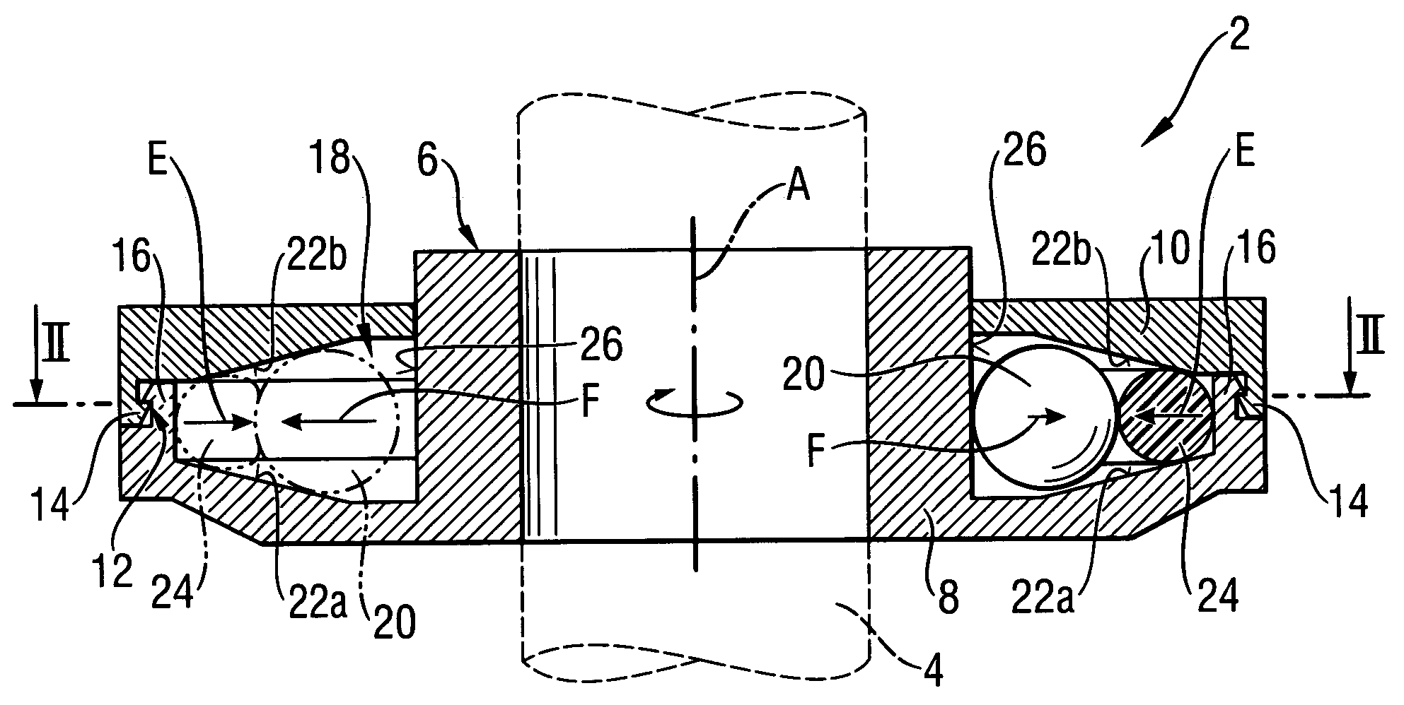
[0022] A balancing device 2 according to the present invention for an automatic balancing of imbalance of a, rotatable about axis A, system in form of a tool spindle 4, shown with dash lines, e.g., of an angular grinder, is shown in FIGS. 1-2 and includes a two-part housing 6 mountable on the tool spindle 4 for joint rotation therewith. The housing 6 has a base part 8 and a cover part 10 which are formlockingly connected with each other by a locking device 12. The locking device 12 has resilient locking means 14 in form of a circumference of the cover part 10 and has a hook-shaped cross-section. The resilient locking means 14 lockingly engages counter locking means 16 which is provided on the base part 8. The counter locking means 16 is likewise formed as a circumferential rim having a hook-shaped cross-section.

[0023] The housing 6 forms, in its interior, a circumferential track 18 about the axis A and in which ball-shaped balancing bodies 20 are arranged. The track 18 is limited, ...


PUM


Abstract

An automatic balancing device for a rotatable system includes a track (18) arranged about a rotational-axis (H) of the rotatable system and having two roll-off surfaces (22a, 22b) inclined toward each other in a direction of a centrifugal force acting (F) acting on at least one balancing body (20) which is received in a free cross-section formed by the two roll-off surfaces (22a, 22b) and limited by an elastic locking element (24) arranged there between for displacing the at least one balancing body (20) away from the roll-off surfaces (22a, 22b) in a direction opposite the direction of the centrifugal force (F) and for pressing the at least one balancing body (20) against an inner boundary of the track (18) for locking the balancing body (20) when a rotational speed of the system is below a predetermined threshold.

Description

BACKGROUND OF THE INVENTION [0001] 1. Field of the Invention [0002] The present invention relates to an automatic balancing device for a rotatable system, in particular, for a hand-held tool such as, e.g., an angular grinder, and including a track which is arranged about the rotational axis of the rotatable system and in which at least one balancing body is displaceably arranged, and an elastic resilient element that presses the at least one balancing body against an inner boundary of the track when the rotational speed of the system is below a predetermined threshold, in order to lock the at least one balancing member against the track inner boundary. [0003] 2. Description of the Prior Art [0004] In balancing devices of the type described above, the at least one balancing body is automatically displaced along the track during the operation of the system under the action of forces acting thereon into a position in which it balances the imbalance of the system. When the rotational sp...

Claims


Application Information

Patent Timeline
IPC IPC(8): G01M1/36B23Q11/00B24B23/02B24B41/04B24B45/00B60B1/00F16C15/00F16F15/36
CPCB24B23/028B24B41/042Y10T74/2128Y10T74/2114F16F15/363
Inventor KOSCHEL, CHRISTIANSPANGENBERG, ROLFLANG, EBERHARD
Owner HILTI AG
Learn More