
Method for designing an uplink pilot signal and a method and a system for estimating a channel in a multicarrier code division multiple access system

a multi-carrier code division and access system technology, applied in the field of mobile communication system, can solve the problems of mc-cdma limitations in uplink transmission applications, the pilot signal or the gi is often distorted, and the reliability of synchronization acquisition is decreased, so as to achieve stable synchronization and minimize the effect of band efficiency reduction

Inactive Publication Date: 2005-09-15
SAMSUNG ELECTRONICS CO LTD +1
View PDF11 Cites 19 Cited by
  • Summary
  • Abstract
  • Description
  • Claims
  • Application Information

AI Technical Summary

Benefits of technology

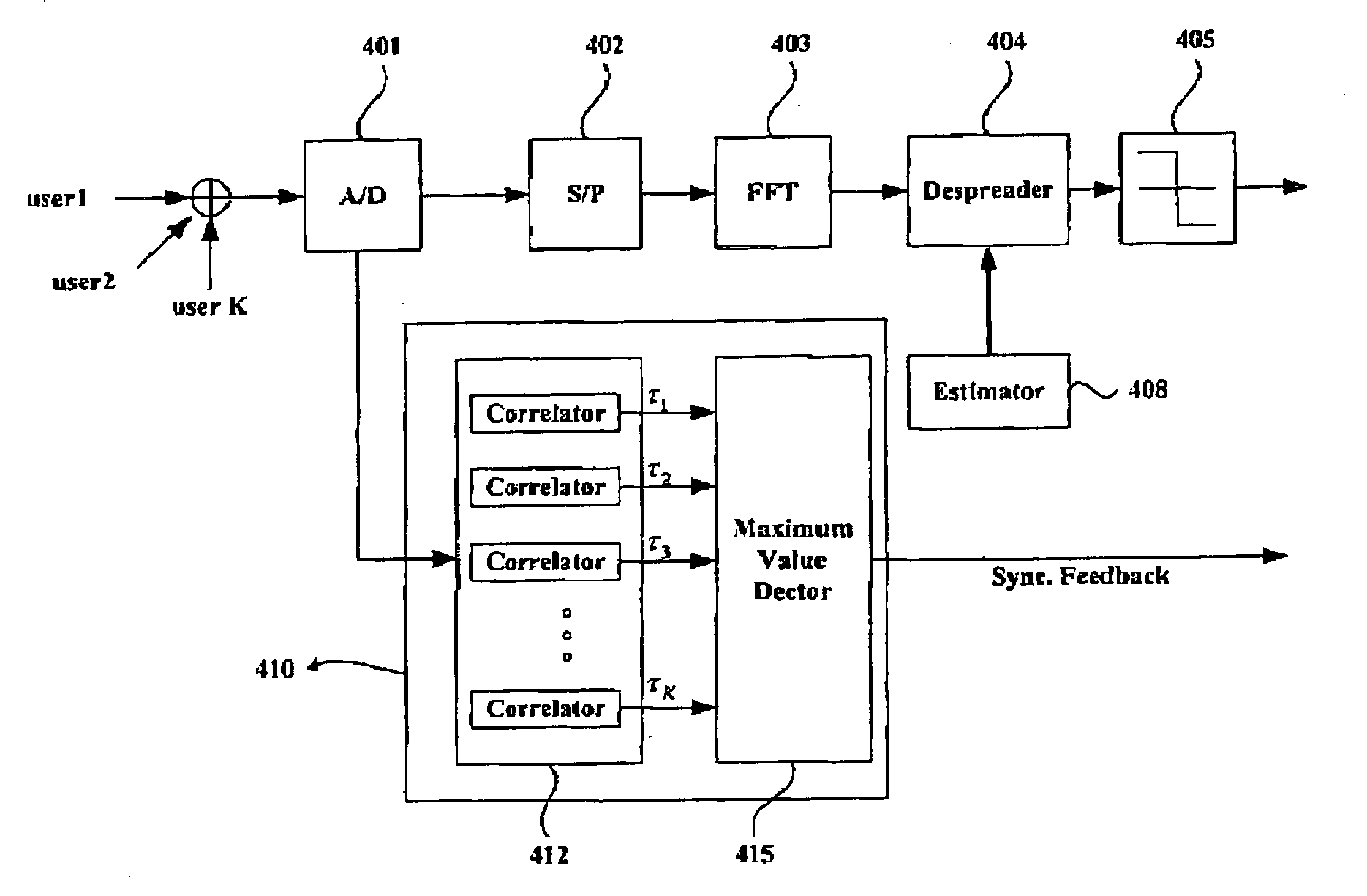
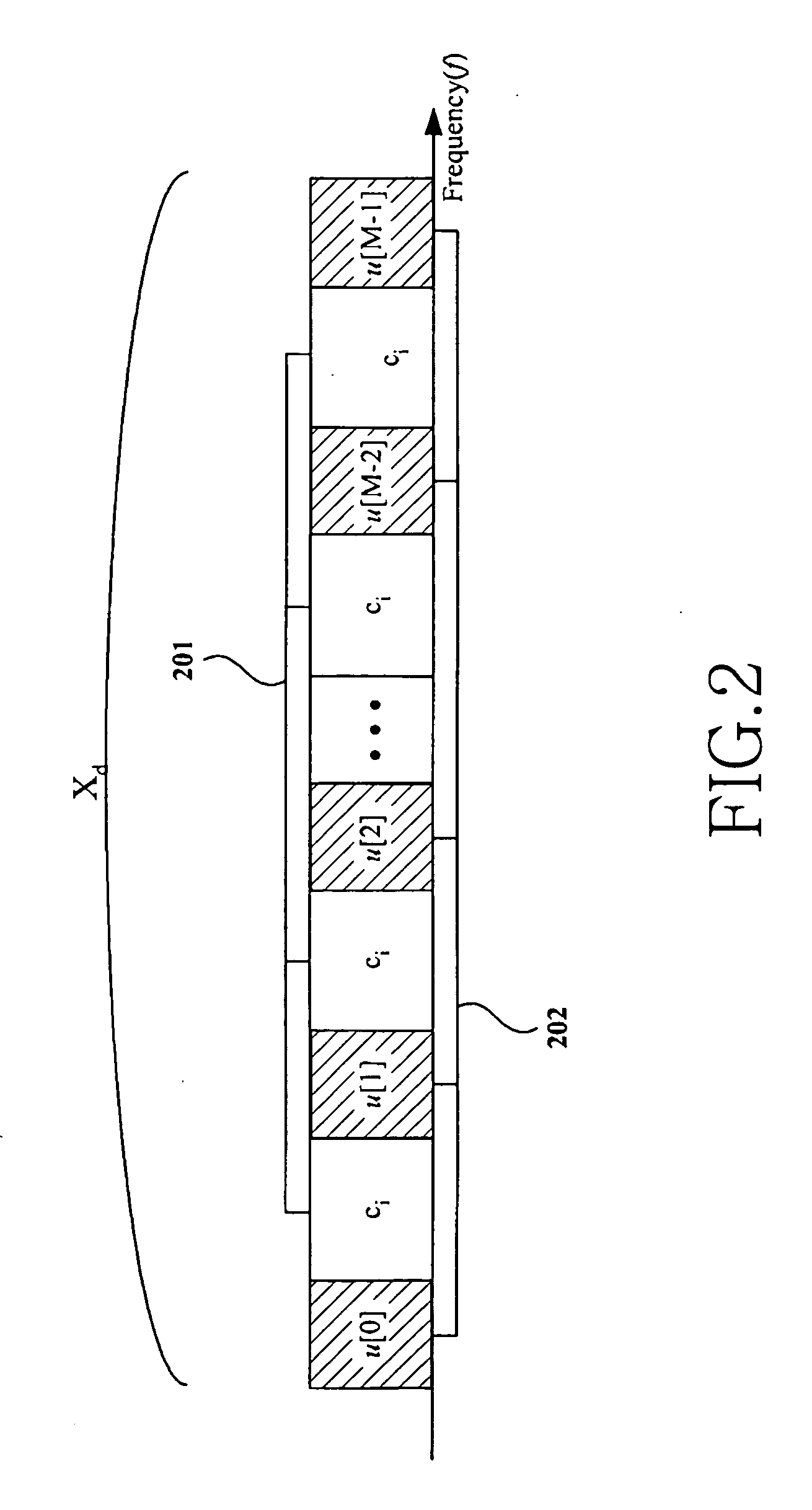
The present invention provides a method for designing an uplink pilot signal in a wireless communication system that can simultaneously support timing synchronization and channel estimation. The pilot signal includes a sync code and a channel characteristic code in a time domain, and an orthogonal code in a frequency domain. The pilot signal also includes a spreading code and a dependent code that are not related to channel estimation. The channel characteristic code is designed to maximize the signal-to-interference and noise ratio (SINR) in the frequency domain. The pilot signal is designed to have predetermined time-domain and frequency-domain responses. The receiver in the base station uses a pilot signal to estimate a channel for each of the multiple mobile stations. The method and system provide stable synchronization and channel estimation, while minimizing the pilot-caused decrease of band efficiency.

Problems solved by technology

However, if the multiple access interference (MAI) caused by signals from multiple users is great, a pilot signal or a GI is often distorted.
As a result, the reliability of the synchronization acquisition is decreased.
MC-CDMA has limitations in applications of uplink transmission under complex propagation conditions, albeit it is accepted as a suitable technology for downlink transmission.
In other words, since signals from a plurality of mobile stations (MSs) are received under different channel transfer functions, pilot-based channel estimation is difficult.
In addition, different velocities of the mobile stations and different distances between MSs and a base station (BS) make uplink synchronization difficult.

Method used


Image

  • Method for designing an uplink pilot signal and a method and a system for estimating a channel in a multicarrier code division multiple access system
  • Method for designing an uplink pilot signal and a method and a system for estimating a channel in a multicarrier code division multiple access system
  • Method for designing an uplink pilot signal and a method and a system for estimating a channel in a multicarrier code division multiple access system

Examples


Embodiment Construction

[0025] A preferred embodiment of the present invention will be described herein below with reference to the accompanying drawings. In the following description, well-known functions or constructions are not described in detail since they would obscure the invention in unnecessary detail.

[0026] According to the present invention, an MC-CDMA uplink pilot signal is designed in such a manner that it includes a sync code in the time domain and enables channel estimation for each user in the frequency domain.

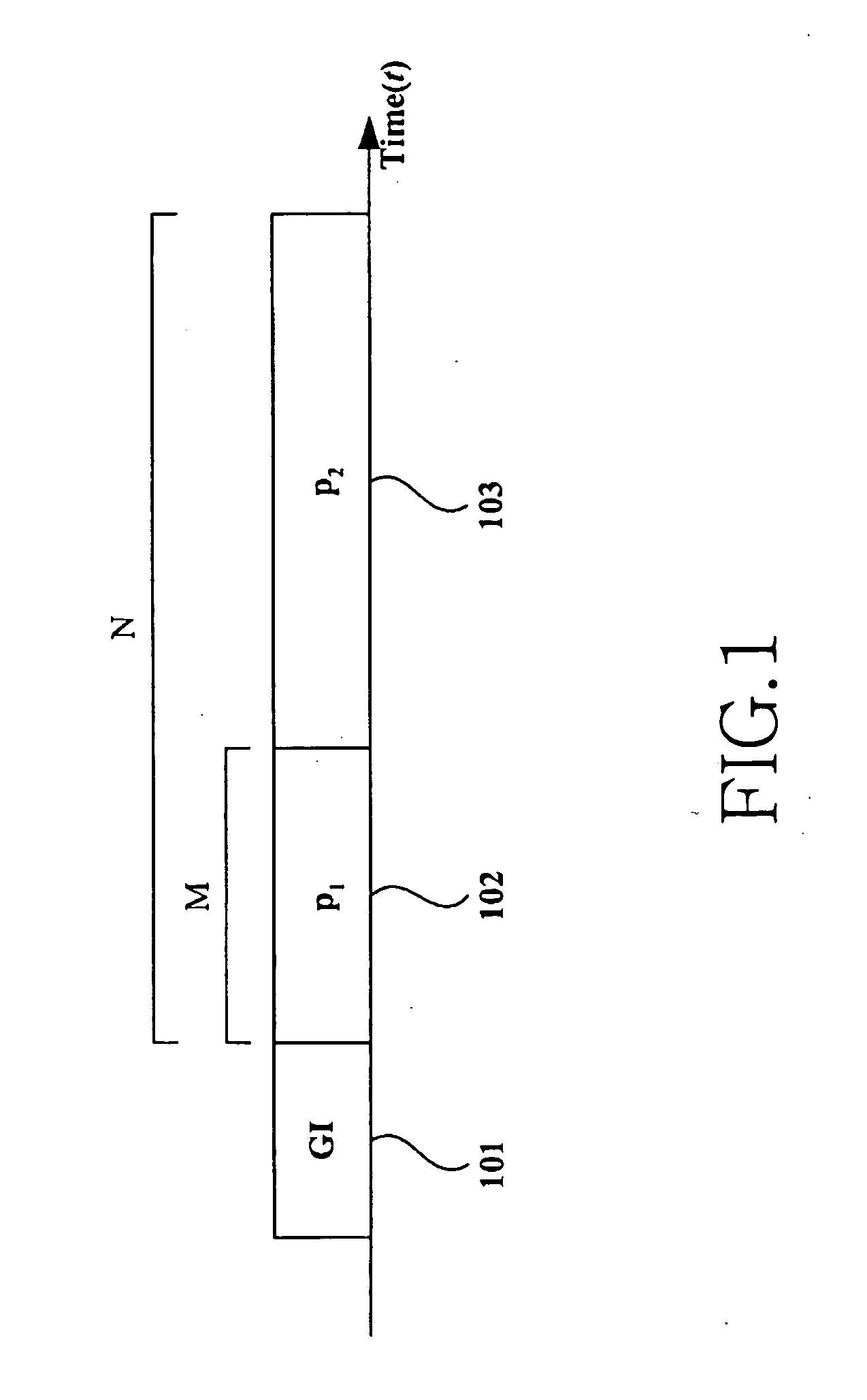
[0027]FIG. 1 illustrates the time-domain structure of a pilot signal designed according to a preferred embodiment of the present invention.

[0028] Referring to FIG. 1, a pilot signal is formed of a GI 101 for removing delay spread, a sync code (p1) 102 for timing synchronization, and a channel characteristic code (p2) 103 designed by taking into consideration the frequency characteristics. The pilot signal having N samples except for the GI 101 is expressed as Equation 1: p=(p1p2)(...


PUM


Abstract

A channel estimating method in a wireless communication system in which a plurality of MSs communicate with a BS on multiple carriers. Each of the MSs transmits to the BS a pilot signal designed to have simultaneous time-domain and frequency-domain responses. The BS is synchronized to the MS using the received pilot signal and performs channel estimation for the MS.

Description

PRIORITY [0001] This application claims priority under 35 U.S.C. § 119 to an application entitled “Method of Designing Uplink Pilot Signal in a MultiCarrier Code Division Multiple Access System” filed in the Korean Intellectual Property Office on Jan. 15, 2004 and assigned Serial No. 2004-3060, the contents of which are incorporated herein by reference. BACKGROUND OF THE INVENTION [0002] 1. Field of the Invention [0003] The present invention relates generally to a mobile communication system, and in particular, to a method for designing a pilot signal for simultaneously supporting synchronization and channel estimation in a multicarrier code division multiple access (MC-CDMA) system. [0004] 2. Description of the Related Art [0005] The future-generation mobile communication system requires high-speed high-quality data transmission for the provisioning of various multimedia services with an improved quality. To satisfy this demand, studies are being actively conducted on the MC-CDMA s...

Claims


Application Information

Patent Timeline
Patent Type & Authority Applications(United States)
IPC IPC(8): H04J11/00H04B1/707H04B1/76H04B7/26H04J13/16H04J13/18H04L25/02H04L27/26H04W56/00H04W76/02H04W92/10
CPCH04L27/2613H04L25/0226H04B1/7073
Inventor MOON, JUNELEE, YONG-HWANYU, HYUN-SEOK
Owner SAMSUNG ELECTRONICS CO LTD
Learn More