Liquid ejection head and liquid ejection device
a liquid ejection device and liquid ejection technology, which is applied in the direction of printing, inking apparatus, etc., can solve the problems of insufficient supply of liquid to the flow path, nozzles b>18/b> may be clogged with dust, and the liquid cannot be ejected from the nozzles
- Summary
- Abstract
- Description
- Claims
- Application Information
AI Technical Summary
Benefits of technology
Problems solved by technology
Method used
Image
Examples
example 1
[0167]FIGS. 14A and 14B are views showing a result that a reduction in impact waves is confirmed (as a result of photographing) in the conventional structure and in the structure of the embodiment.
[0168] In an example 1, a semiconductor substrate 11, on which 320 heating elements 12 are disposed at 600 DPI (nozzle intervals are set to 4.2 μm), is used (size: about 16 mm×16 mm).
[0169] A nozzle sheet 17 composed of a transparent acrylic resin is used so that an internal behavior can be observed. The result of experiment shown in FIGS. 14A and 14B corresponds to the view shown in FIG. 12.
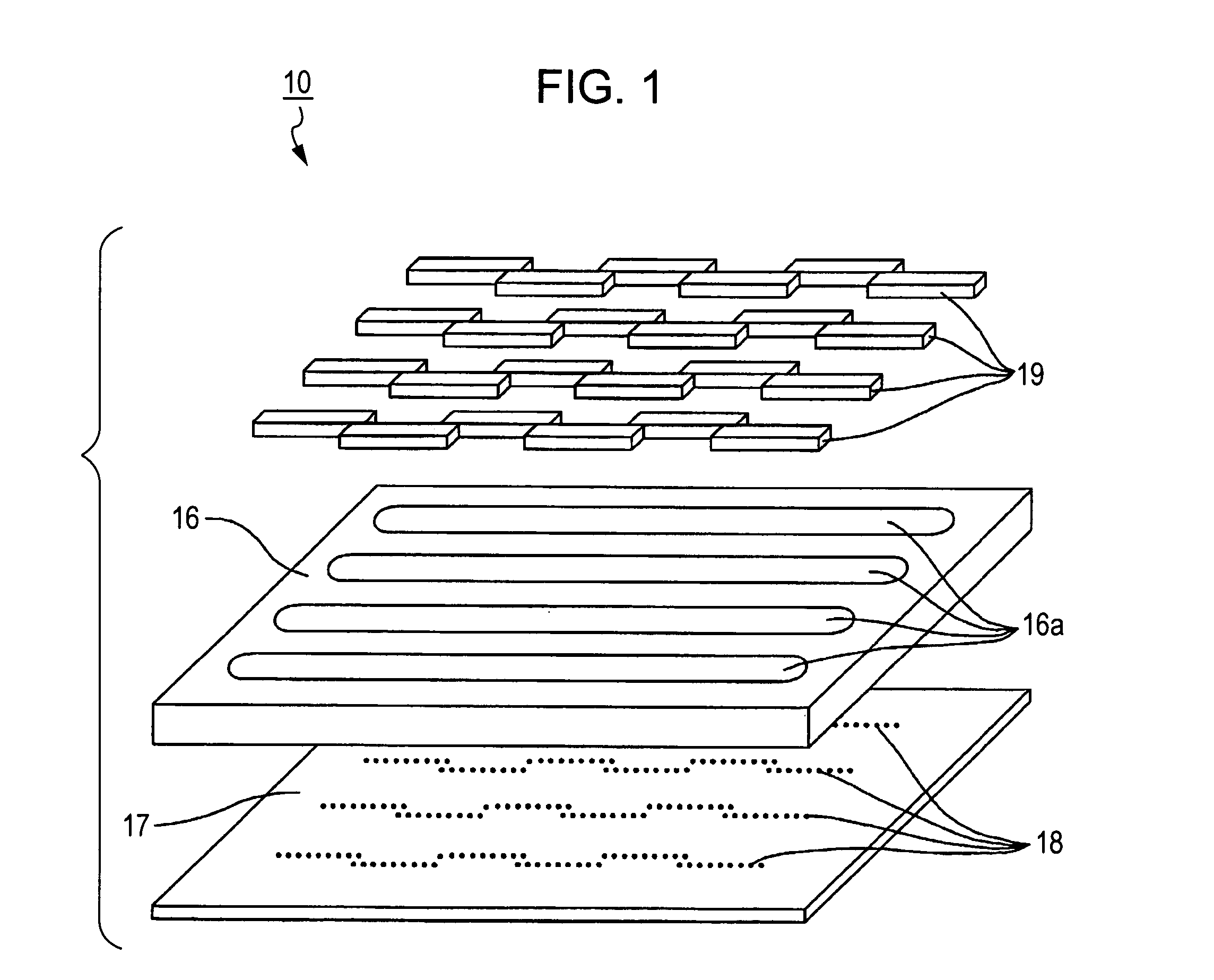
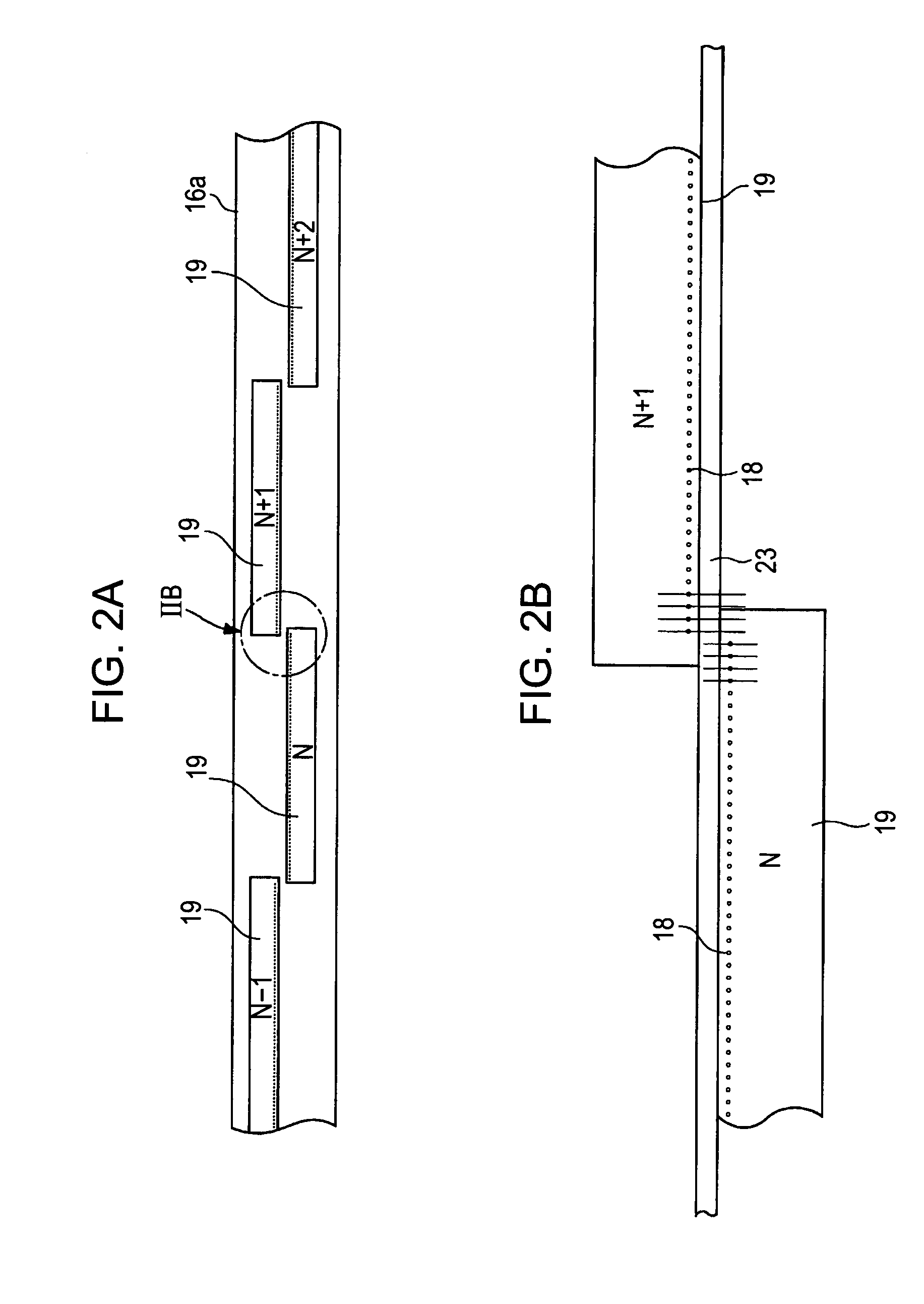
[0170] In the conventional structure of FIG. 14B, nozzles 18 arranged linearly. In contrast, in the example, nozzles 18 are arranged zigzag as described above.
[0171] In FIGS. 14A and 14B, the nozzles 18 seem black just after they eject the liquid because a liquid surface is intensely fluctuated by the influence of impact waves. Although the longitudinal lines of the heating elements 12 disposed bel...
example 2
[0172]FIG. 15 is a plan view showing a specific structure of a head used in an example 2. As shown in FIG. 15, the head used in the example 2 is provided with a liquid storage region 28 having pillars 28a interposed between the outlets of the second individual flow paths 13e and the wall of the barrier layer 13. A filter 25 disposed in a common flow path 23 is the same as the filter 25 shown in FIG. 9.
[0173]FIG. 16 is a view showing how bubbles are discharged using a head having the structure shown in FIG. 15 as a result sequential photographing. FIG. 16 shows the behavior of bubbles discharged in the sequence of “1”, “2” . . . “9”.
[0174] In “1” of FIG. 16, bubbles were injected from the nozzles, and the space between the liquid storage region 28 and the second individual flow paths 13e was clogged with the bubbles. Then, when a liquid ejecting operation was repeated using a third nozzle 18 from the left side as shown in “1”, the bubbles were gradually discharged from the nozzle 1...
example 3
[0175]FIGS. 17A and 17B are views showing a part of a mask view of a prototype head (nozzle pitch: 42.3 μm, resolution: 600 DPI). In FIGS. 17A and 17B, an upper side is a common flow path 23 side.
[0176]FIG. 17A shows an example corresponding to the arrangement shown in FIG. 11 (the second embodiment described later in detail), FIG. 17B shows an example corresponding to the arrangement shown in FIG. 3.
[0177] That is, In FIG. 17A, adjacent second individual flow paths 13e communicate with each other. Further, FIG. 17B, all the second individual flow paths 13e communicate with each other.
[0178] Further, the filter 25 is composed of triangular-prism-shaped pillars. Further, the heating elements are arranged zigzag.
[0179] When images were actually printed with the heads, burst errors (wide portions with uneven color and voided portions in monochrome), which were liable to appear in the conventional structure when a temperature increased in continuous printing or when print was execut...
PUM
 Abstract
Description
Claims
Application Information
 - R&D
- Intellectual Property
- Life Sciences
- Materials
- Tech Scout
- Unparalleled Data Quality
- Higher Quality Content
- 60% Fewer Hallucinations
Browse by: Latest US Patents, China's latest patents, Technical Efficacy Thesaurus, Application Domain, Technology Topic, Popular Technical Reports.
© 2025 PatSnap. All rights reserved.Legal|Privacy policy|Modern Slavery Act Transparency Statement|Sitemap|About US| Contact US: help@patsnap.com


