Facility management computer system operable for receiving data over a network generated by users and sensors

Inactive Publication Date: 2005-09-08
SMITH RENATO L
View PDF62 Cites 244 Cited by
  • Summary
  • Abstract
  • Description
  • Claims
  • Application Information

AI Technical Summary

Benefits of technology

[0017] At the same time, the computer system enables the manager of the facility to use the website as a fully functional facility management system. Accordingly, the manager can manually enter, store, organize and retrieve property management data at the website. The sensor-generated data is integrated with the manually input data. Therefore, the computer system enables the facility manager to access information and reports which incorporate sensor data. This assists the facility managers in increasing the efficiency of operating the facility, minimizing loss and damage to the facility and maximizing profits. Wall-Mountable Computer
[0037] Yet another object of the present invention is to decrease the thickness of a computer having a keyboard which is adapted to be mounted to a wall or other upstanding member.

Problems solved by technology

Many of the challenges in the facility management industry relate to information, that is, the flow of information involving facility conditions and facility users.
As described below, the known technology fails to adequately maintain or facilitate the flow of this information.
This can result in a decrease in the quality and safety of the facility as well as a decline in the profitability of facility operations.
In many cases, if the manager discovers a defect early enough, the manager can have the repair made before significant collateral damage occurs to the facility: For many facilities, due to the size of the building, limitations on the manager's resources or the type of commercial activity, there may be a significant delay before the manager receives notice of a defect.
For example, in an apartment building, the manager's access to the apartments is restricted.
If the tenant is unaware of or otherwise fails to report a water leak, the manager may not learn of the leak until the leak causes costly water damage to another apartment.
The known facility management software, however, does not accommodate sensor technology.
Despite this advancement, this conventional software has failed to evolve with the relatively recent use of sensor technology in buildings and other facilities.
However, as stated earlier, the known facility management software does not have the functionality to accommodate the sensor technology.
Information can be lost in the transfer of data from the sensor system to the facility management system.
In addition, the facility owner or management company must incur the labor cost associated with operating and maintaining both systems and transferring the sensor data to the property management system.
This labor cost can be relatively high for larger facilities.
Furthermore, because the sensor system is not the main system used by the manager, there is the risk that the manager will not check the sensor system as often as necessary to receive defect reports from the sensors in a timely fashion.
Another disadvantage of the known technology relates to the existing method of communication between the manager and the facility users.
One disadvantage with this method is that tenants sometimes misplace mailings or overlook bulletin board postings.
As a result, managers may have to reschedule appointments, and the tenants may lose important information.
This can result in increased administrative costs, lost income and increased exposure to liability for personal injury and other claims.
Another disadvantage with this method is that tenants often find it too inconvenient or too time consuming to mail or fax a notice to the manager.
Many tenants also find it too inconvenient or time consuming to email a notice to the manager using a conventional computer.
This can lead to disputes regarding the exact content of the notice which, in turn, can lead to increased administrative costs and tenant dissatisfaction.

Method used


Image

  • Facility management computer system operable for receiving data over a network generated by users and sensors
  • Facility management computer system operable for receiving data over a network generated by users and sensors
  • Facility management computer system operable for receiving data over a network generated by users and sensors

Examples


Embodiment Construction

I. Facility Management Computer System

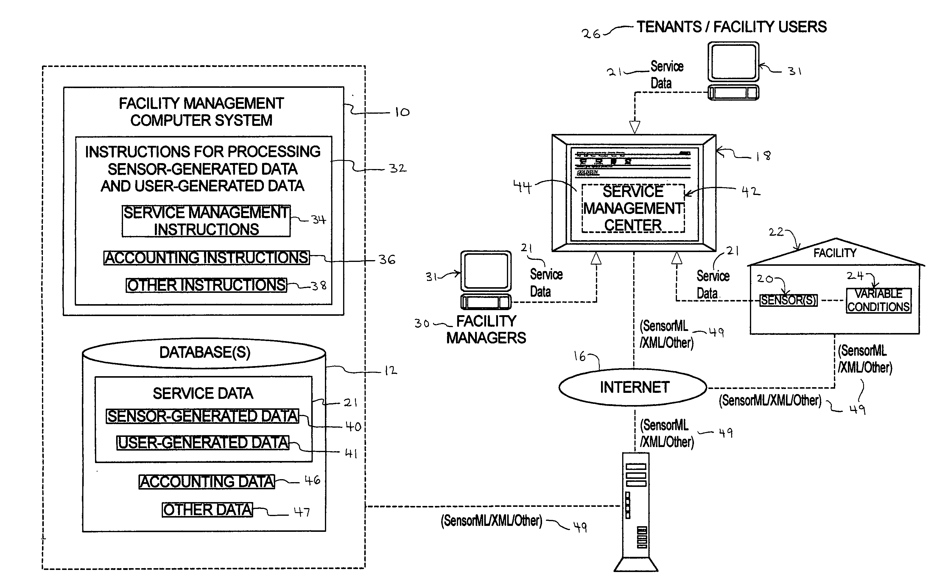
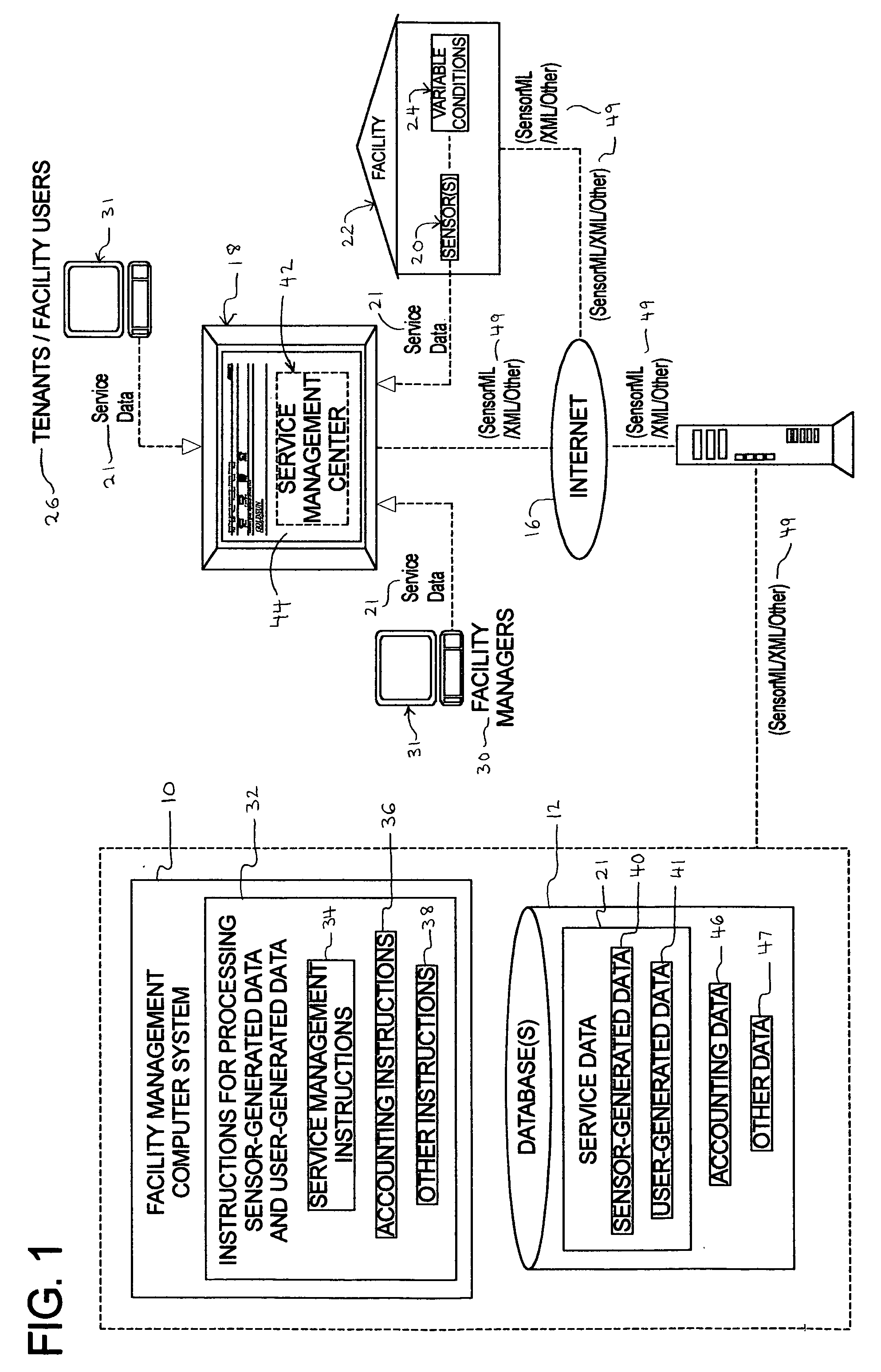
[0068] Referring now to the drawings, FIG. 1 illustrates the facility management computer system 10 of the present invention used in conjunction with one or more databases 12. The computer system 10 directs one or more servers 14, operating on a network, such as the Internet 16, to control or host a graphical user interface (GUI), such as a website 18. Through the Internet 16, the server 14 is also in communication with one or more sensors 20. The sensors 20 are located at or in one or more buildings, parcels of real property or facilities 22.

[0069] In one embodiment, the facility 22 includes a structure or building including, without limitation, a multi-unit apartment building or complex, a multi-unit condominium building or complex, a house, residential housing, a dormitory, a hospital, a long term or short term healthcare facility, a train station, a sports stadium, a concert hall or an entertainment hall. In another embodiment, the facility...


PUM


Abstract

A facility management computer system which, in one embodiment, controls a website that provides users with access to user-generated data and sensor-generated data. The computer system is used in conjunction with a facility having at least one sensor for sensing variable conditions of the facility. The computer system integrates the sensor-generated data with non-sensor data, such as data related to facility description, facility users, facility income and facility expenses. Such a computer system assists facility managers in increasing the efficiency of operating facilities and minimizing loss and damage to facilities.

Description

CROSS REFERENCE TO RELATED APPLICATIONS [0001] This application is related to the following commonly-owned co-pending patent application: “Wall-Mountable Computer Having an Integrated Keyboard,” Attorney Docket No. 200-02. COPYRIGHT NOTICE [0002] A portion of the disclosure of this patent document contains or may contain material which is subject to copyright protection. The copyright owner has no objection to the photocopy reproduction by anyone of the patent document or the patent disclosure in exactly the form it appears in the Patent and Trademark Office patent file or records, but otherwise reserves all copyright rights whatsoever. BACKGROUND OF THE INVENTION [0003] Many of the challenges in the facility management industry relate to information, that is, the flow of information involving facility conditions and facility users. As described below, the known technology fails to adequately maintain or facilitate the flow of this information. This can result in a decrease in the q...

Claims


Application Information

Patent Timeline
CPCG06Q10/06G06Q50/163G06Q20/10
Inventor SMITH, RENATO L.
Owner SMITH RENATO L
Why Eureka
Try Eureka