
Ceramic metal halide lamp with optimal shape

a ceramic metal halide and optimal shape technology, applied in the field of electric lamps, can solve the problems of depletion of filler constituents, certain reactive properties of fused quartz, and high operating temperature, and achieve the effect of improving performance and li

Inactive Publication Date: 2005-09-08
GENERAL ELECTRIC CO
View PDF9 Cites 33 Cited by
  • Summary
  • Abstract
  • Description
  • Claims
  • Application Information

AI Technical Summary

Benefits of technology

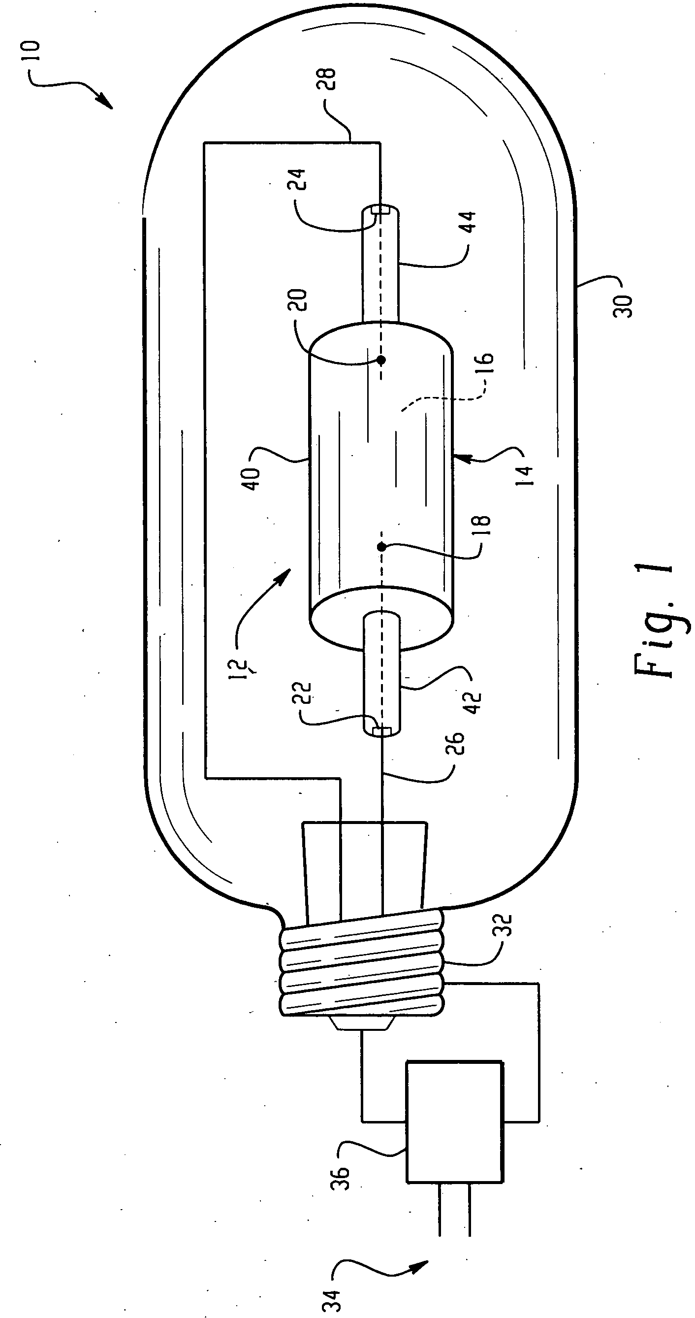
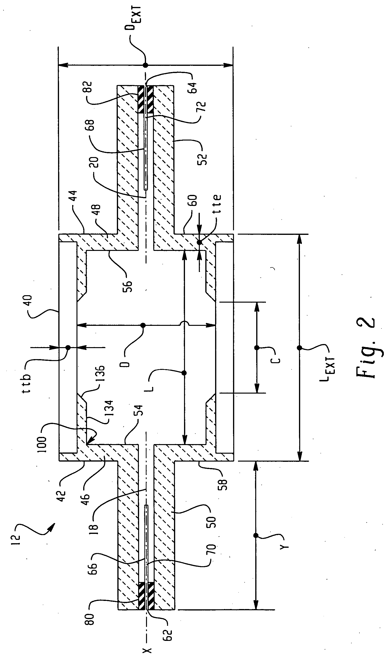
"The present invention provides a lighting assembly with a ceramic arctube and a lamp that operates at a power of greater than 200 W. The arctube has optimized structural elements such as dimensions, and an ionizable fill is disposed inside the arctube. The lamp includes a ballast and a lamp electrically connected with the ballast. The arctube is designed to have an internal space with a ratio of internal length to internal diameter of 1.5 to 2.0. The ceramic arctube has improved performance and life compared to previous designs. The method of forming the lighting assembly involves providing a cylindrical discharge vessel with electrodes and an ionizable fill. The arctube wall loading is optimized, and the ceramic wall thickness, aspect ratio, and halide weight are defined. The technical effects of the invention include improved performance and life of the ceramic arctube, optimized structural elements, and improved lighting assembly."

Problems solved by technology

Fused quartz, however, has certain disadvantages which arise from its reactive properties at high operating temperatures.
For example, in a quartz lamp, at temperatures greater than about 950-1000° C., the halide filling reacts with the glass to produce silicates and silicon halide, which results in depletion of the filler constituents.
Elevated temperatures also cause sodium to permeate through the quartz wall, which causes depletion of the filler.
Both depletions cause color shift over time, which reduces the useful lifetime of the lamp.
Despite improvements, commercially available vessels for CMH lamps tend to have poor performance in terms of lumen output, color separation, and horizontal cracking when operated at high wattage.

Method used


Image

  • Ceramic metal halide lamp with optimal shape
  • Ceramic metal halide lamp with optimal shape
  • Ceramic metal halide lamp with optimal shape

Examples


example 1

[0059] Arctubes are formed according to the shape shown in FIG. 2 from three component parts, as illustrated in FIG. 4. A fill comprising 20.6% NaI, 2.1%Tl, 12.8% DyI3, 6.5% HoI3, 6.5% TmI3, 0.8% CeI3, 48% CaI2, and 2.7% CsI is used. The metal halide arctubes are back filled with a rare gas, comprising Ar and a small addition of Kr85. The cold fill pressure is 130 Torr. The arctubes are assembled into lamps having an outer vacuum jacket and a quartz shroud to contain possible arctube rupture, and which are run on North American “Pulse Arc” ballasts. The arctube leg geometry, leadwire design, seal parameters, and outer jacket are the same for all lamps tested, except that the 320 W has different electrodes.

[0060] Lamps formed as described above are run in a vertical orientation (i.e., as illustrated in FIG. 3) with the lamp cap positioned uppermost. TABLE 1 illustrates properties of the lamps and properties during operation. Each data point represents an average of a population of l...

example 2

[0065] Arctubes are formed as for Example 1. according to the shape shown in FIG. 2 from three component parts, as illustrated in FIG. 4. A fill comprising by weight 35.3% NaI, 4.9% TlI, 6.3% DyI3, 3.2% HoI3, 3.2% TmI3, 41.6% CaI2 and 5.5% CsI is used. The metal halide arctubes are back filled with a rare gas, comprising Ar and a small addition of Kr85. The cold fill pressure is 130 Torr. The arctubes are assembled into lamps having an outer vacuum jacket and are run on a HPS ballast. The arctube leg geometry, leadwire design, seal parameters, and outer jacket are the same for all lamps tested. Small changes to the design of the electrode accommodate the different arc currents at the different power loads.

[0066] Lamps formed as described above are run either in a vertical orientation VBU (i.e., as illustrated in FIG. 3) with the lamp cap positioned uppermost, or in a horizontal orientation HOR (as illustrated in FIG. 2). TABLE 2 illustrates properties of the lamps and properties du...


PUM

PropertyMeasurementUnit
poweraaaaaaaaaa
thicknessaaaaaaaaaa
power factoraaaaaaaaaa

Abstract

A metal halide lamp (10) has a ceramic arctube (12) with an inside length L, an inside diameter D, and an aspect ratio L / D of between about 1.5 and about 2.0 containing a suitable fill. The lamp may have a power rating of 200 W or more and can be used with an existing ballast.

Description

BACKGROUND OF THE INVENTION [0001] The present invention relates to an electric lamp having a ceramic arctube enclosing a discharge space having a length L, a diameter D, and an aspect ratio L / D which minimizes wall corrosion while providing extended life and improved performance. [0002] Discharge lamps produce light by ionizing a vapor filler material such as a mixture of rare gases, metal halides and mercury with an electric arc passing between two electrodes. The electrodes and the filler material are sealed within a translucent or transparent discharge chamber which maintains the pressure of the energized filler material and allows the emitted light to pass through it. The filler material, also known as a “dose”, emits a desired spectral energy distribution in response to being excited by the electric arc. For example, halides provide spectral energy distributions that offer a broad choice of light properties, e.g. color temperatures, color renderings, and luminous efficacies. [...

Claims


Application Information

Patent Timeline
Patent Type & Authority Applications(United States)
IPC IPC(8): H01J9/24H01J61/30H01J61/36H01J61/56H01J61/82
CPCH01J9/247H01J61/125H01J61/56H01J61/302H01J61/36H01J61/20
Inventor DAKIN, JAMES T.BUGENSKE, MATTHEWUTTERBACK, GARY W.
Owner GENERAL ELECTRIC CO
Learn More