
Electronic device, failure prediction method, and computer product

a technology of failure prediction and electronic devices, applied in the direction of instruments, nuclear elements, nuclear engineering, etc., can solve the problems of system failure, higher failure rate of parts, and increased possibility of system failure due to breakdown of constituent parts

Inactive Publication Date: 2005-09-01
FUJITSU LTD
View PDF6 Cites 24 Cited by
  • Summary
  • Abstract
  • Description
  • Claims
  • Application Information

AI Technical Summary

Benefits of technology

[0010] It is an object of the present invention to s...

Problems solved by technology

The possibility of a system failure due to breakdown of constituent parts has increased in recent electronic devices, such as an information apparatus or a communication apparatus, because of large scale and high rate of integration of the system.
For instance, a blade server that realizes a high-density mounting includes more number of parts, such as several hundred scales of CPUs, than a conventional server, which may cause a higher rate of part failure.
Although a method such as a dual operation of a system is employed to avoid the system failure, there still is a system failure occurred due to a complex failure interacted with a latent failure in the system.
However, the accuracy of the statistical method is dependent on a quality of the operation model, and it is difficult to make a model of all operations of a complex semiconductor device with a large-scale.
Besides, the accuracy of the statistical method is also dependent on setting a threshold value when determining a difference between an actual operation and the operation model, and it is also extremely difficult to set a proper threshold value.
The method using the redundant circuit is not better than a statistical method, having a problem of a considerable error caused by a variation in the parts, subtle differences in the test environment, etc.
Furthermore, regarding running of a system, it is not easy to replace a part of questionable life expectancy in a normally operation status of a circuit of interest.

Method used


Image

  • Electronic device, failure prediction method, and computer product
  • Electronic device, failure prediction method, and computer product
  • Electronic device, failure prediction method, and computer product

Examples


first embodiment

[0043]FIG. 2 is a block diagram of a blade server according to the present invention. A blade server 100 includes a hard disk 110, a temperature setting unit 120, an error detecting unit 130, and a control unit 140.

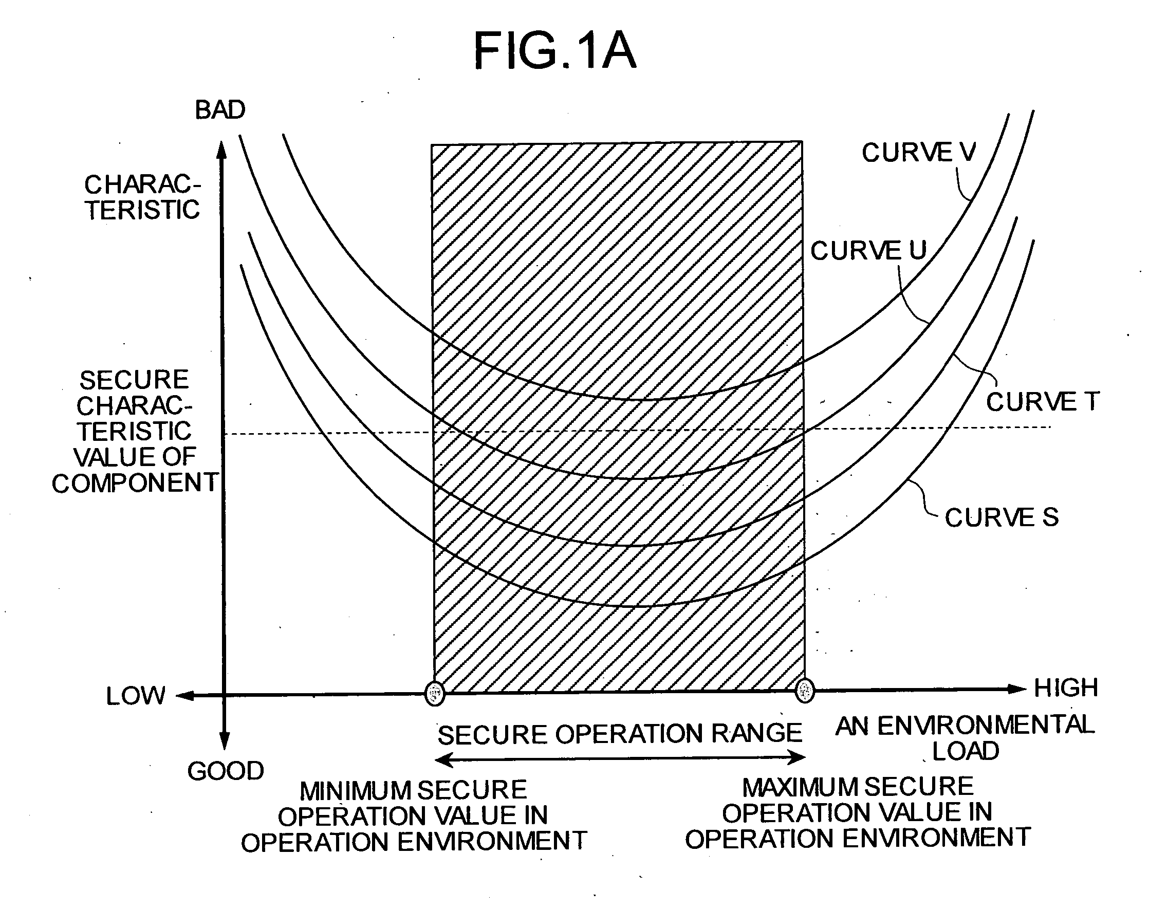
[0044] The hard disk 110 is the part to which a temperature load is applied by the temperature setting unit 120 and for which failure prediction is to be carried out. FIG. 3 is a graph of an error rate of a hard disk 110 in response to a temperature load.

[0045] Generally, a maximum temperature and a minimum temperature for absolute rating, and a maximum temperature and a minimum temperature for secure operation are stipulated as operating conditions for all electronic parts such as the hard disk 110. The absolute rating is a value which when exceeded results in the possibility of a breakdown of the part. The secure operation temperature value is a temperature value which when exceeded does not guarantee a normal operation.

[0046] In other words, a normal part may not fun...

second embodiment

[0082] To be more specific, a temperature load can be applied on the electronic parts by controlling the fan or a heat pump provided for cooling the electronic parts. For instance, a temperature load can be applied by slowing down or stopping the fan. In the electronic device explained in the present invention, the temperature load tests are carried out by applying temperature load by means of controlling the cooling of the electronic part.

[0083]FIG. 7 is a block diagram of an electronic device according to a second embodiment of the present invention. An electronic device 200 includes an electronic part 210, a cooling unit 220, an error detecting unit 230, and a control unit 240.

[0084] The electronic part 210 is a part that realizes the device functions, and for which failure prediction is to be carried out. The cooling unit 220 is functional part that cools the electronic part 210. The error detecting unit 230 is a functional part that detects malfunctioning in the electronic par...

third embodiment

[0089]FIG. 8 is a block diagram of an electronic device according to the present invention. An electronic device 300 includes a communication processing part 310, a test data applying unit 320, and error detecting unit 330, a control unit 340, and a test data separating unit 350.

[0090] The communication processing part 310 is a part that carries out communication processing, and for which failure prediction is to be carried out. The test data applying unit 320 is a processing unit that adds test data to regular data in order to increase the processing load of the communication processing part 310. The error detecting unit 330 is a functional unit that detects error generated in the communication processing part 310.

[0091] The control unit 340 includes a temperature controller 341, a secure operation value storing unit 342, error data collecting unit 343, secure operation value testing unit 344, a non-secure operation value testing unit 345, a threshold value history storing unit 34...


PUM


Abstract

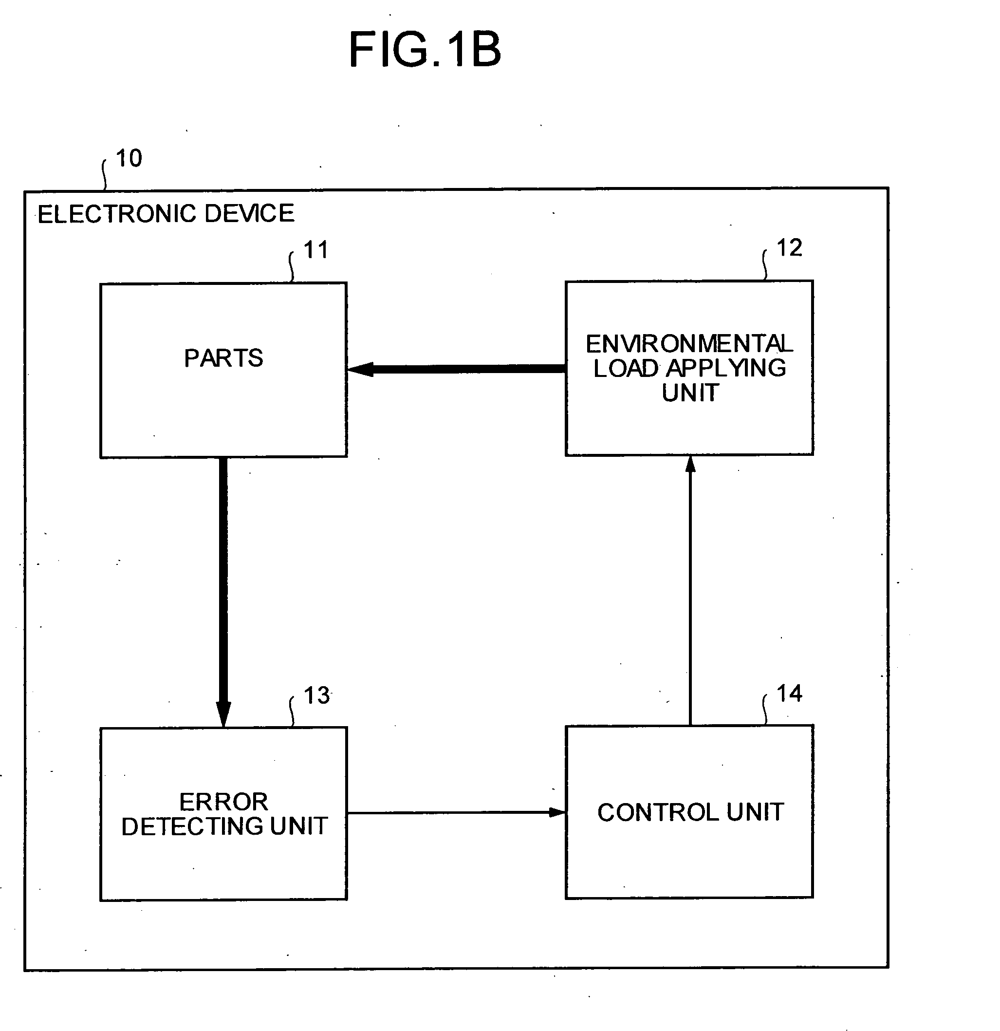
An electronic device that includes a part prone to aged deterioration includes an environmental load applying unit that applies a higher environmental load on the part than an environmental load in a normal operation, an error detecting unit that detects an error in the part with the higher environmental load applied, and a failure predicting unit that predicts a failure of the part based on the error detected.

Description

BACKGROUND OF THE INVENTION [0001] 1) Field of the Invention [0002] The present invention relates to a technology for predicting a failure of a part that is prone to aged deterioration in an electronic device by directly detecting a signal of impending failure of the part. [0003] 2) Description of the Related Art [0004] The possibility of a system failure due to breakdown of constituent parts has increased in recent electronic devices, such as an information apparatus or a communication apparatus, because of large scale and high rate of integration of the system. For instance, a blade server that realizes a high-density mounting includes more number of parts, such as several hundred scales of CPUs, than a conventional server, which may cause a higher rate of part failure. Although a method such as a dual operation of a system is employed to avoid the system failure, there still is a system failure occurred due to a complex failure interacted with a latent failure in the system. [000...

Claims


Application Information

Patent Timeline
IPC IPC(8): G01R31/00G06F11/00G06F11/24G06F19/00G06Q10/04
CPCG06F11/24
Inventor YASUO, AKIHIRO
Owner FUJITSU LTD
Learn More