
In-plane switching liquid crystal display device having extraordinary polarizers

a liquid crystal display and in-plane switching technology, applied in non-linear optics, instruments, optics, etc., can solve the problems of limiting the kinds of application environments in which the ips-lcd can be used, unable to work at temperatures higher than 80 degrees centigrade, and easily damaged or even destroyed in handling or in use, etc., to achieve thin and compact

Inactive Publication Date: 2005-09-01
INNOLUX CORP
View PDF21 Cites 8 Cited by
  • Summary
  • Abstract
  • Description
  • Claims
  • Application Information

AI Technical Summary

Benefits of technology

[0010] Accordingly, an object of the present invention is to provide a liquid crystal display device which has a wide view angle, which can work at high temperatures, and which is relatively thin and compact.

Problems solved by technology

Because the polarizers are made of PVA, they cannot work at temperatures higher than 80 degrees Centigrade.
This limits the kinds of application environments in which the IPS-LCD can be used.
In addition, because the polarizers are both positioned as outer surfaces of the IPS-LCD, they are easily damaged or even destroyed in handling or in use.
This makes the IPS-LCD unduly thick and bulky.

Method used


Image

  • In-plane switching liquid crystal display device having extraordinary polarizers
  • In-plane switching liquid crystal display device having extraordinary polarizers
  • In-plane switching liquid crystal display device having extraordinary polarizers

Examples


Embodiment Construction

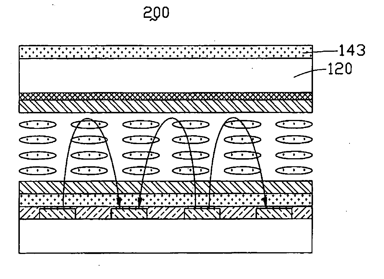
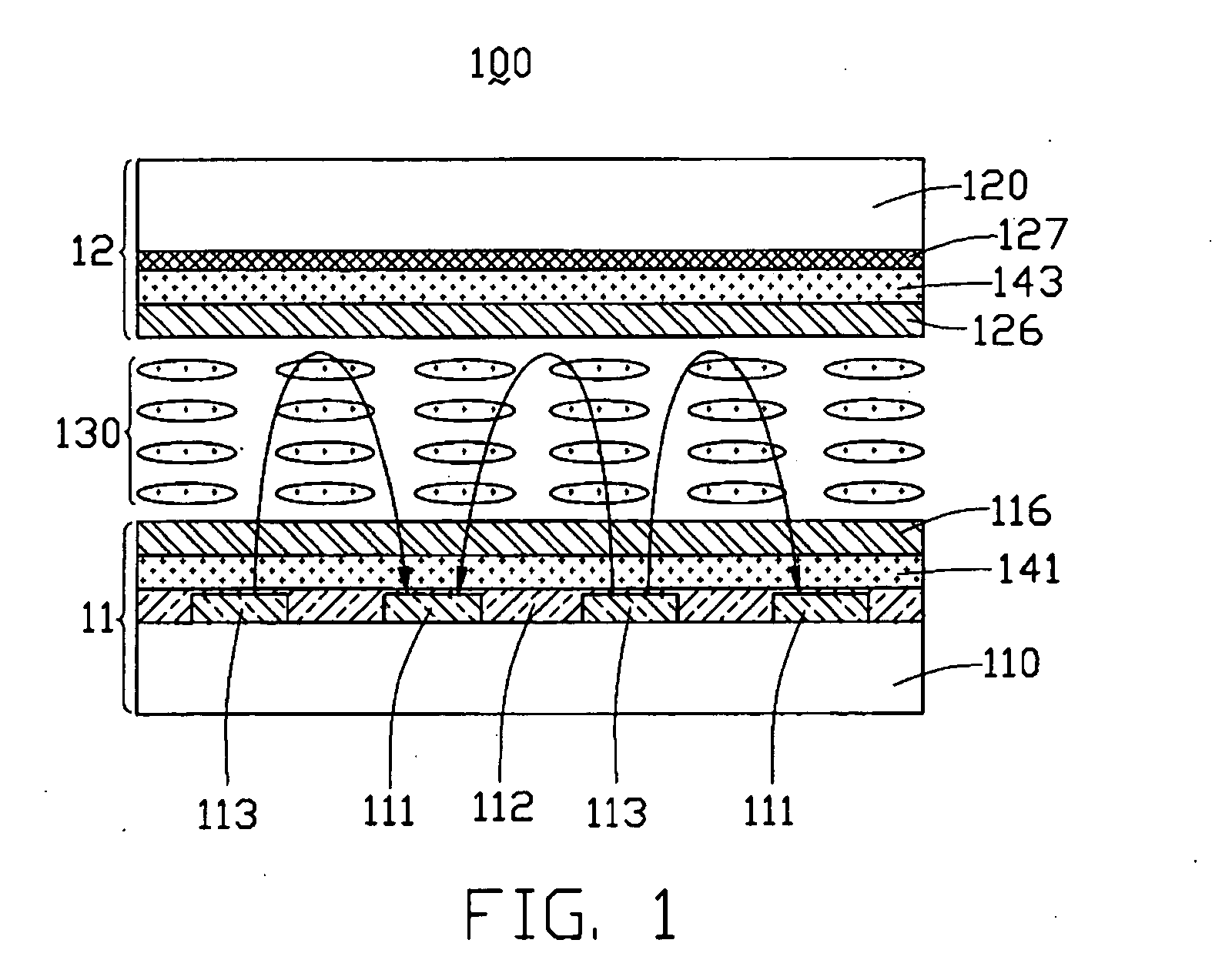
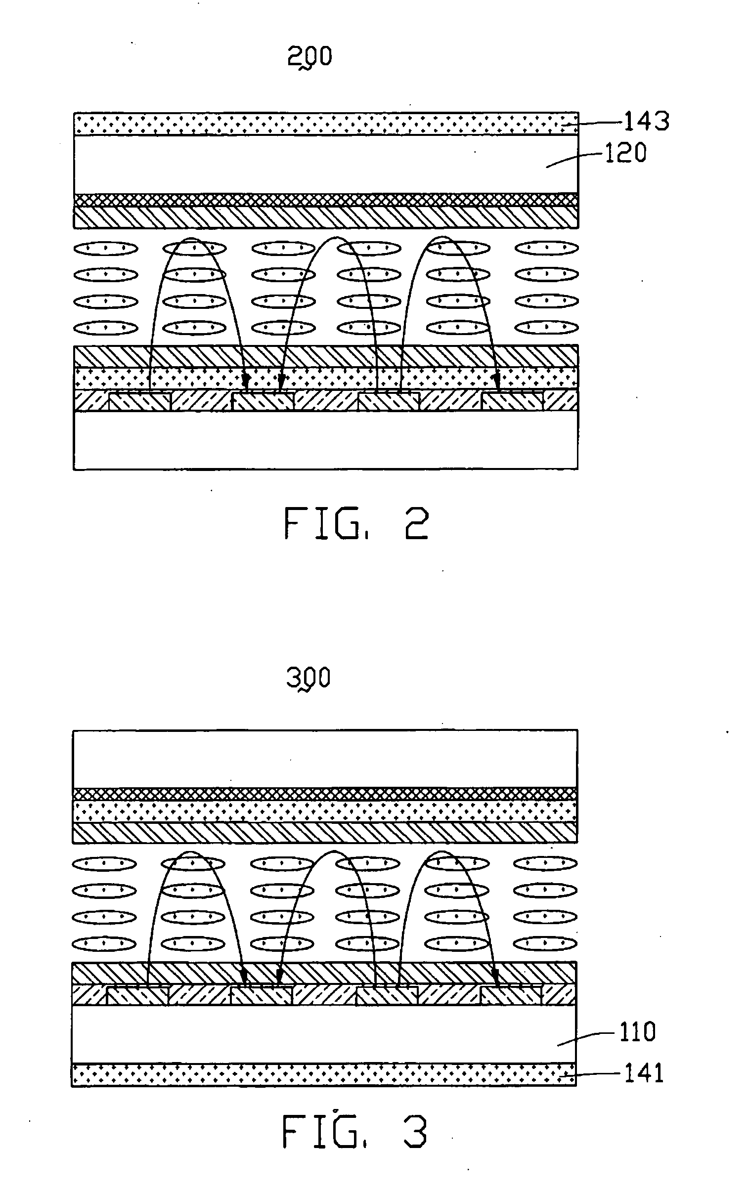
[0017] Referring to FIG. 1, a liquid crystal display device 100 of the first embodiment (“Example 1”) according to the present invention includes an upper substrate 12, a lower substrate 11, and a liquid crystal layer 130 interposed between the upper substrate 12 and the lower substrate 11. The upper substrate 12 comprises a color filter layer 127, an upper polarizer 143 and an upper alignment film 126 positioned in that order from top to bottom on an inner surface of an upper glass plate 120. The lower substrate 11 comprises a multiplicity of pairs of a pixel electrode 113 and a common electrode 111, an insulating layer 112, a lower polarizer 141 and a lower alignment film 116 positioned in that order from bottom to top on an inner surface of a lower glass plate 110. The lower substrate 11 may comprise a thin film transistor (TFT) array (not shown) connecting with the pixel electrodes 113. In an alternative embodiment, the upper glass plate 120 and the lower glass plate 110 can be ...


PUM

PropertyMeasurementUnit
thicknessaaaaaaaaaa
temperaturesaaaaaaaaaa

Abstract

A liquid crystal display device (100) includes an upper substrate (12), a lower substrate (11), and a liquid crystal layer (130) interposed between the upper substrate and the lower substrate. An upper polarizer (143) and a lower polarizer (141) are positioned at the upper and lower substrates respectively, with at least one of the polarizers being an extraordinary type polarizer. A multiplicity of pixel electrodes (113) and common electrodes (111) are positioned at either the upper substrate or the lower substrate, for applying a voltage to the liquid crystal layer. The display device has a wide viewing angle, can work at high temperatures, and is relatively thin and compact.

Description

CROSS REFERENCE TO RELATED APPLICATIONS [0001] This application is related to two co-pending applications both entitled “In-plane switching transflective liquid crystal display device,” and both being assigned to the same assignee as this application. BACKGROUND OF THE INVENTION [0002] 1. Field of the Invention [0003] The present invention relates to liquid crystal displays, and more particularly to an in-plane switching liquid crystal display device having at least one extraordinary type polarizer. [0004] 2. Description of the Prior Art [0005] The in-plane switching liquid crystal display (IPS-LCD) has been developed in order to improve on the narrow viewing angle of the more traditional twisted nematic liquid crystal display (TN-LCD). Typically, the IPS-LCD is a transmissive mode LCD, which utilizes a backlight for illuminating the display screen. The IPS-LCD comprises an upper substrate and a lower substrate disposed opposite to each other and spaced apart a predetermined distanc...

Claims


Application Information

Patent Timeline
Patent Type & Authority Applications(United States)
IPC IPC(8): G02F1/1335G02F1/1343
CPCG02F1/134363G02F1/133528
Inventor YANG, CHIU-LIEN
Owner INNOLUX CORP
Learn More