Magnetron drive power supply

a technology of magnet drive and power supply, applied in the direction of pulse technique, ignition automatic control, instruments, etc., can solve the problems of modulation waveform deviation and failure of high-frequency inverter, and achieve the effect of low cos

Inactive Publication Date: 2005-09-01
PANASONIC CORP
View PDF9 Cites 4 Cited by
  • Summary
  • Abstract
  • Description
  • Claims
  • Application Information

AI Technical Summary

Benefits of technology

[0006] It is therefore an object of the invention to provide a magnetron drive power supply which is resistant to change in the power supply environment and can operate stably.
[0010] Thus, it is made possible to continue the operation with safety if short-time instantaneous power interruption of the commercial power supply occurs, and the magnetron drive power supply that can stably operate without stopping an inverter unnecessarily can be realized.
[0012] Thus, it is made possible to stop the inverter with safety if comparatively long-time instantaneous power interruption of the commercial power supply occurs, and the magnetron drive power supply that can operate without a failure caused by a power outage can be realized.
[0014] Thus, it is made possible to detect the power supply voltage lowering without detecting the input voltage, and the magnetron drive power supply having the voltage lowering protection function can be realized at low cost.
[0016] Thus, it is made possible to detect the input voltage of the commercial power supply lowering almost at constant voltage independently of the input current, and the magnetron drive power supply having the voltage lowering protection function can be realized at low cost.

Problems solved by technology

However, in the magnetron drive power supply in the related art, if the zero voltage detection shifts due to noise, instantaneous power interruption, etc., the modulation waveform deviates from the essential timing and a possibility of leading to a failure of the high-frequency inverter because of overvoltage, overcurrent, etc., occurs.

Method used


Image

  • Magnetron drive power supply
  • Magnetron drive power supply
  • Magnetron drive power supply

Examples


first embodiment

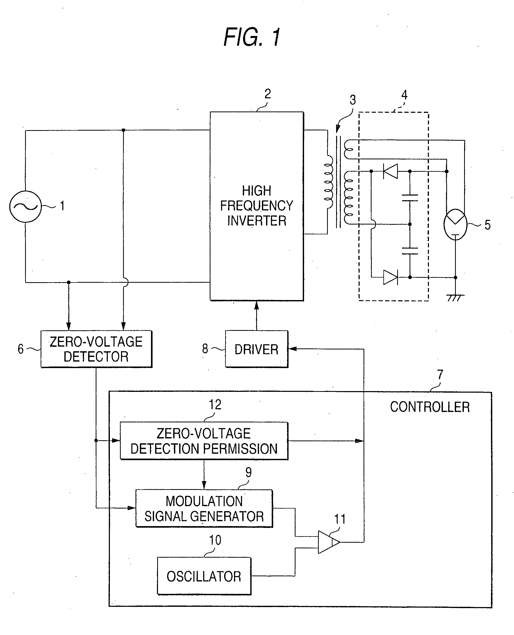
[0027] A first embodiment of the invention will be discussed with reference to the accompanying drawings (FIGS. 1 and 2). FIG. 1 shows the circuit configuration of a magnetron drive power supply of the first embodiment of the invention. Parts identical with those previously described with reference to FIG. 8 are denoted by the same reference numerals in FIG. 1 and will not be discussed again in detail.

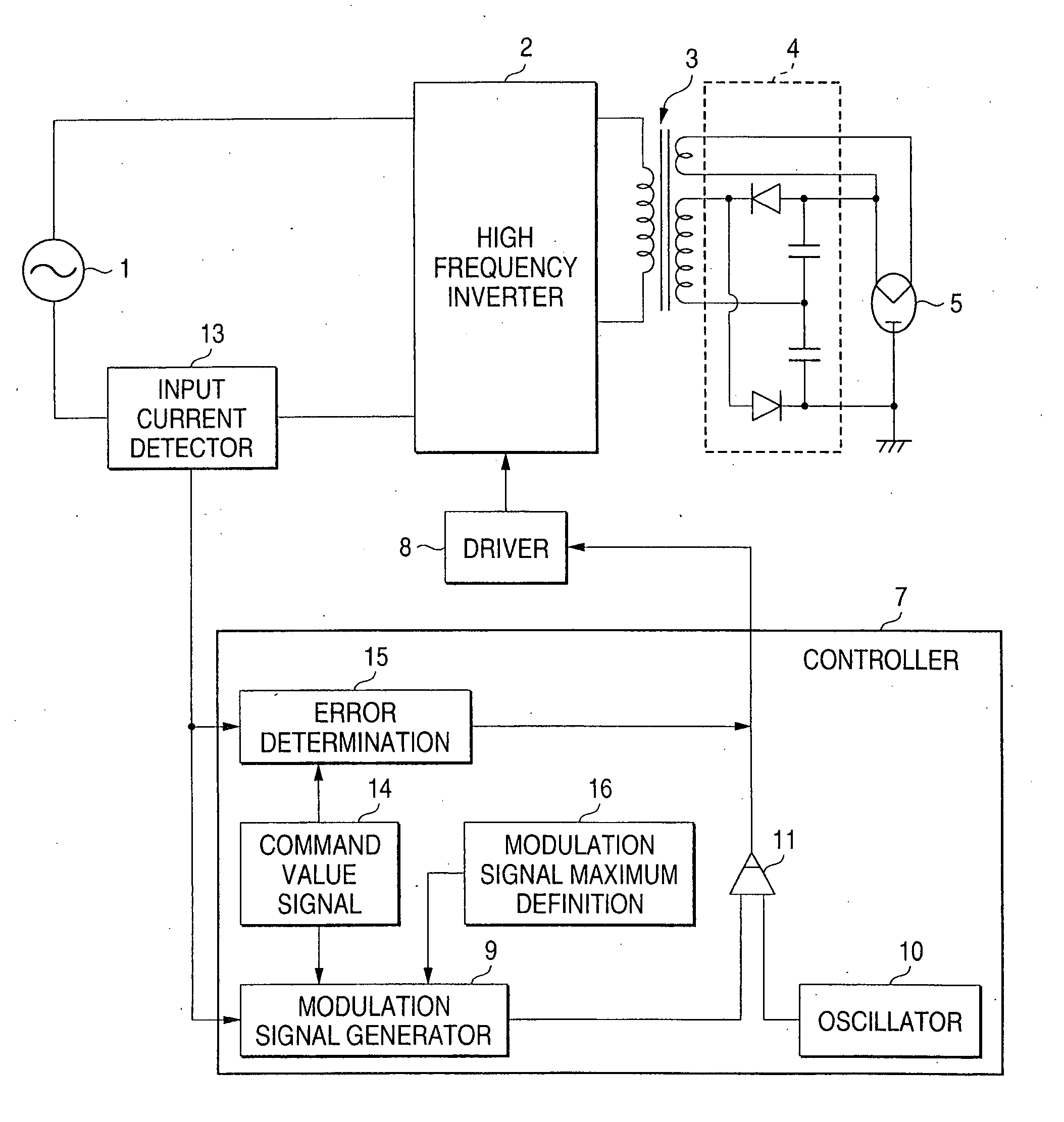
[0028] In FIG. 1, a commercial power supply 1 transmits high-frequency power through a high-frequency inverter 2 to a high-voltage transformer 3. A high-voltage rectification circuit 4 is connected to secondary winding output of the high-voltage transformer 3 for applying a DC high voltage to a magnetron 5. The magnetron 5 generates a 2.45-GHz radio wave based on the DC high voltage. Zero-voltage detector 6 which detects the timing of zero voltage of the commercial power supply is connected to an output section of the commercial power supply 1 and further controller 7 which controls t...

second embodiment

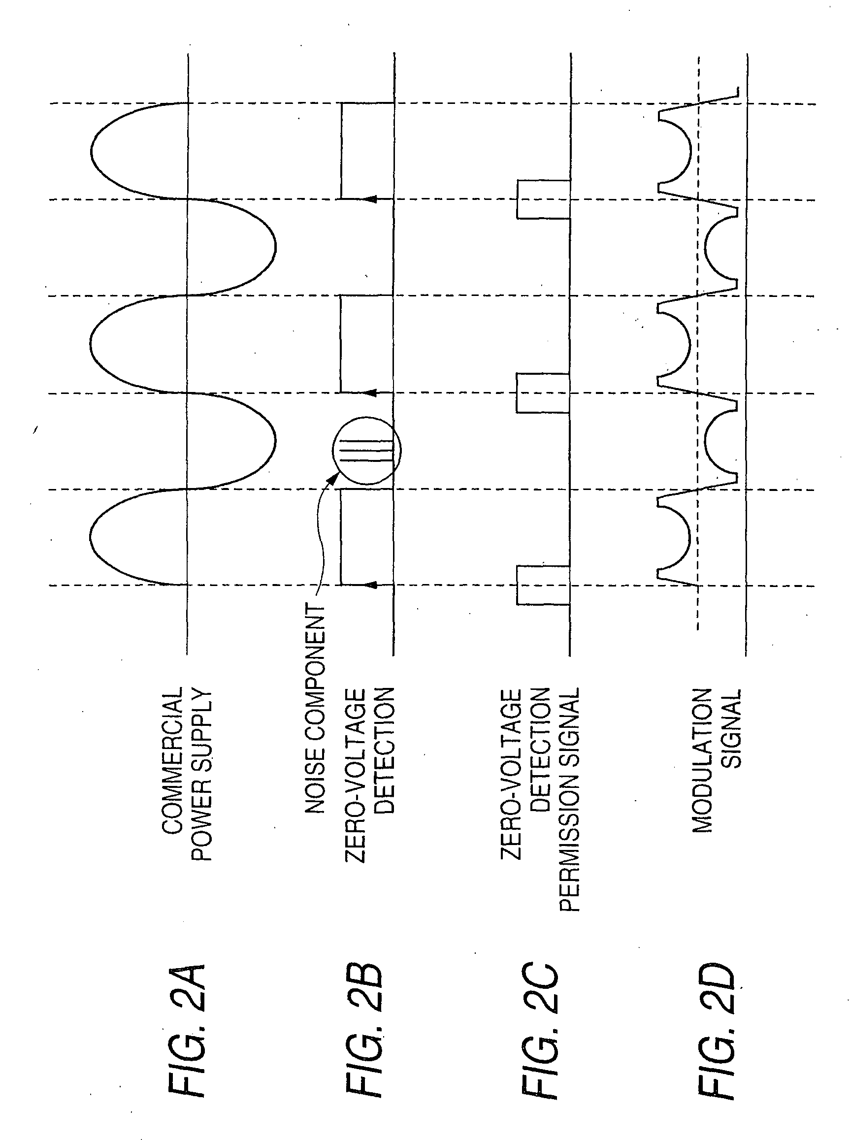
[0034] A second embodiment of the invention will be discussed with reference to the accompanying drawing (FIGS. 3A to 3D). FIGS. 3A to 3D show operation waveforms of a magnetron drive power supply of the second embodiment of the invention. The circuit configuration of the embodiment is similar to that previously described with reference to FIG. 1 and detailed description of reference numerals, etc., is not given.

[0035] As shown in FIGS. 3A to 3D, in the second embodiment, if a signal does not come at the timing at which a signal from zero-voltage detector 6 should essentially come, due to instantaneous power interruption, etc., of commercial power supply (FIG. 3A) (zero-voltage waveform shown in (FIG. 3B)), controller 7 predicts the timing at which the zero-voltage detection signal comes, and outputs a modulation signal (FIG. 3D) by assuming that the zero-voltage signal comes at the timing. Accordingly, it is made possible to continue the operation with safety if short instantaneou...

third embodiment

[0037] A third embodiment of the invention will be discussed with reference to the accompanying drawing (FIGS. 4A to 4E). FIGS. 4A to 4E show operation waveforms of a magnetron drive power supply of the third embodiment of the invention. The circuit configuration of the embodiment is similar to that previously described with reference to FIG. 1 and detailed description of reference numerals, etc., is not given.

[0038] As shown in FIGS. 4A to 4E, in the third embodiment, if commercial power supply (FIG. 4A) enters a power outage state for a comparatively long time because of instantaneous power interruption, etc., namely, if a signal from zero-voltage detector 6 does not come exceeding the stipulated number of times, controller 7 determines that instantaneous power interruption occurs, and stops a high-frequency inverter 2. Accordingly, it is made possible to stop the inverter with safety when comparatively long instantaneous power interruption occurs. The system of determining the o...


PUM


Abstract

Timing of zero voltage in zero-voltage detector for detecting zero voltage of a commercial power supply 1 is predicted and input from the zero-voltage detector 6 is received only for a given time before and after the predicted timing, whereby overvoltage and overcurrent caused by a zero point shift can be prevented. Thus, it is provided a magnetron drive power supply which is excellent in stability for change in the power supply environment such as noise or instantaneous power interruption.

Description

BACKGROUND OF THE INVENTION [0001] This invention relates to a magnetron drive power supply with a magnetron of a microwave oven, etc., as a load. [0002] A magnetron drive power supply in a related art will be discussed with reference to the accompanying drawings (FIGS. 8 and 9). FIG. 8 is a circuit block diagram of a magnetron drive power supply in a related art. A semiconductor switch in a high-frequency inverter 2 is controlled by controller 7, whereby a commercial power supply 1 is converted into radio-frequency power of 20 to 50 kHz and the radio-frequency power is supplied to a high-voltage transformer 3. A high-voltage rectification circuit 4 and a magnetron 5 are connected to the secondary side of the high-voltage transformer 3 and a DC high voltage is applied to the magnetron 5 for generating a 2.45-GHz radio wave. [0003] Zero-voltage detector 6 detects a zero voltage point of the power supply voltage 1 and causes modulation signal generator 9 to generate a modulation wave ...

Claims


Application Information

Patent Timeline
Patent Type & Authority Applications(United States)
IPC IPC(8): H05B6/66H05B6/68
CPCH05B6/666H05B6/68
Inventor KITAIZUMI, TAKESHISUENAGA, HARUOMORIYA, HIDEAKIISHIZAKI, EMIKO
Owner PANASONIC CORP
Why Eureka
Try Eureka