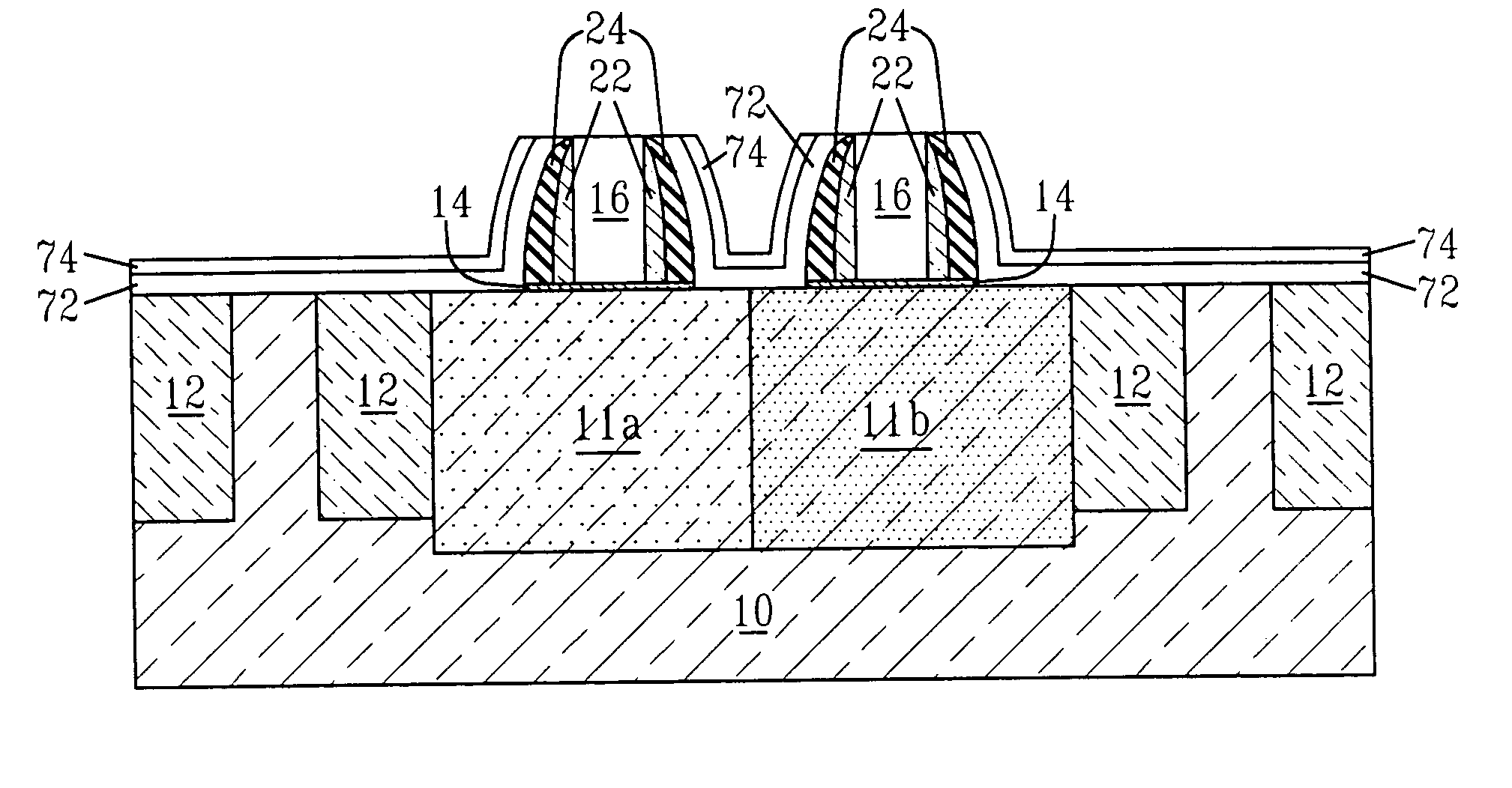
CMOS silicide metal gate integration
a metal gate and silicide technology, applied in the direction of transistors, semiconductor devices, electrical equipment, etc., can solve problems such as non-uniform performance, and achieve the effect of reducing processing complexity and not increasing the production cost of cmos transistors
- Summary
- Abstract
- Description
- Claims
- Application Information
AI Technical Summary
Benefits of technology
Problems solved by technology
Method used
Image
Examples
first embodiment
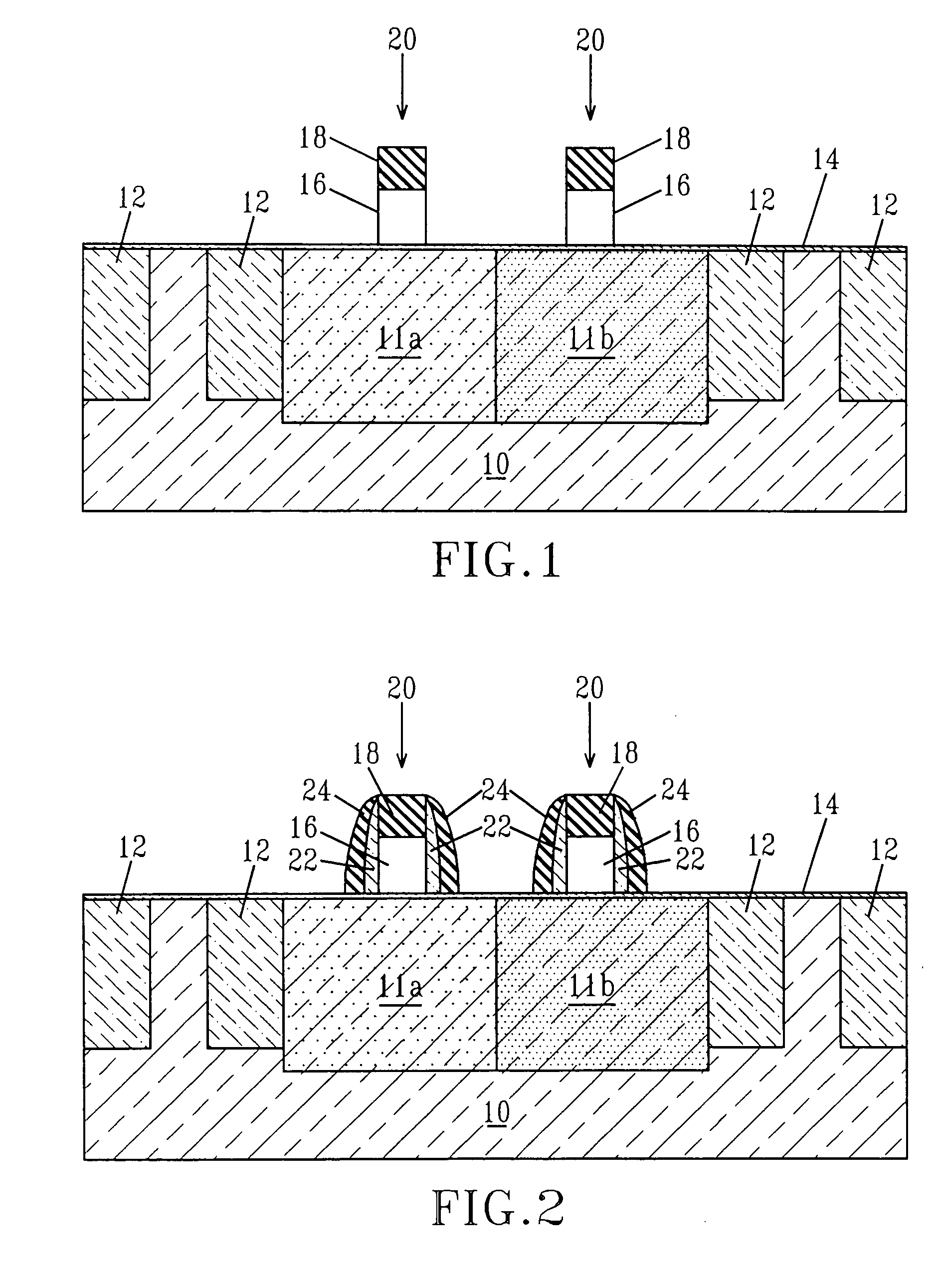
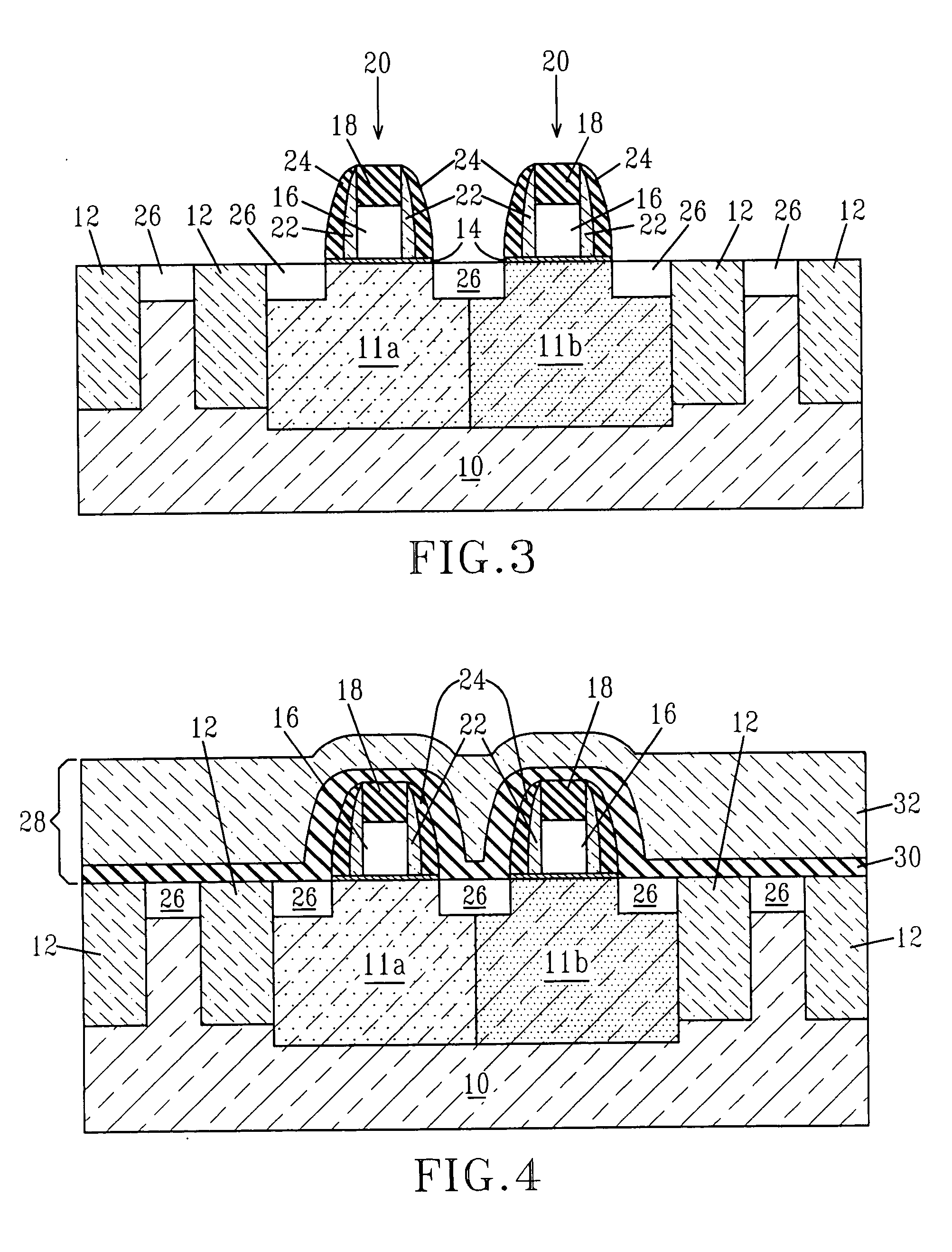
[0053] Reference is made to FIGS. 1-10, which are cross sectional views of a CMOS structure during various stages of the present invention. Although the drawings show the presence of two polySi gates (i.e., a CMOS transistor structure with pFET and nFET transistors), the present invention is not limited to that number of polySi gates. Instead, the present integration process works for any number of polySi gates. Hence, a plurality of polySi gates may be present across a single semiconductor structure.
[0054]FIG. 1 shows an initial structure that is employed in the first embodiment of the present invention. Specifically, the initial structure shown in FIG. 1 comprises semiconductor substrate 10 having isolation regions 12 formed therein. The initial structure also includes a gate dielectric 14 located on top of the semiconductor substrate 10 as well as on top of the isolation regions 12. This is the case if the dielectric is deposited as for a high k material, but not if the dielectri...
second embodiment
[0090] Reference is made to FIGS. 11A-11E, which are cross sectional views of a CMOS structure during various stages of the present invention. Although these drawings show the presence of two polySi gates (i.e., a CMOS transistor structure with pFET and nFET transistors), the present invention is not limited to that number of polySi gates. Instead, the present integration process works for any number of polySi gates. Hence, a plurality of polySi gates may be present across a single semiconductor structure.
[0091]FIG. 11A shows an initial structure that can be employed in the second embodiment of the present invention. As shown, the initial structure includes a semiconductor substrate 10, patterned gate dielectric 14 located on a surface of the semiconductor substrate 10, a patterned polySi gate 16 located atop a surface portion of the patterned gate dielectric 14 and spacers 23 formed on exposed vertical sidewalls of each patterned polySi gate 16. The structure shown in FIG. 11A incl...
third embodiment
[0102] Reference is made to FIGS. 12A-12F, which are cross sectional views of a CMOS structure during various stages of the present invention. Although these drawings show the presence of two polySi gates (i.e., a CMOS transistor structure with pFET and nFET transistors), the present invention is not limited to that number of polySi gates. Instead, the present integration process works for any number of polySi gates. Hence, a plurality of polySi gates may be present across a single semiconductor structure.
[0103]FIG. 12A shows an initial CMOS structure that can be employed in the second embodiment of the present invention. As shown, the initial structure includes a semiconductor substrate 10 having first doped region 11a, second doped region 11b and isolation regions 12 formed therein, patterned gate dielectric 14 located on a surface of the semiconductor substrate 10, a patterned polySi gate 16 located atop a surface portion of the patterned gate dielectric 14 and spacers 22 and 24 ...
PUM
| Property | Measurement | Unit |
|---|---|---|
| temperature | aaaaa | aaaaa |
| temperature | aaaaa | aaaaa |
| temperature | aaaaa | aaaaa |
Abstract
Description
Claims
Application Information
 - R&D
- Intellectual Property
- Life Sciences
- Materials
- Tech Scout
- Unparalleled Data Quality
- Higher Quality Content
- 60% Fewer Hallucinations
Browse by: Latest US Patents, China's latest patents, Technical Efficacy Thesaurus, Application Domain, Technology Topic, Popular Technical Reports.
© 2025 PatSnap. All rights reserved.Legal|Privacy policy|Modern Slavery Act Transparency Statement|Sitemap|About US| Contact US: help@patsnap.com


