
Aluminum conductor composite core reinforced cable and method of manufacture

a technology of aluminum conductors and composite cores, applied in the field of aluminum conductor composite core reinforced cables and methods of manufacture, can solve the problems of acsr cables suffering from thermal expansion and a reduction in tensile strength, coiled sag below permissible levels, and excessive line sag

Inactive Publication Date: 2005-08-25
CTC GLOBAL CORP
View PDF35 Cites 117 Cited by
  • Summary
  • Abstract
  • Description
  • Claims
  • Application Information

AI Technical Summary

Benefits of technology

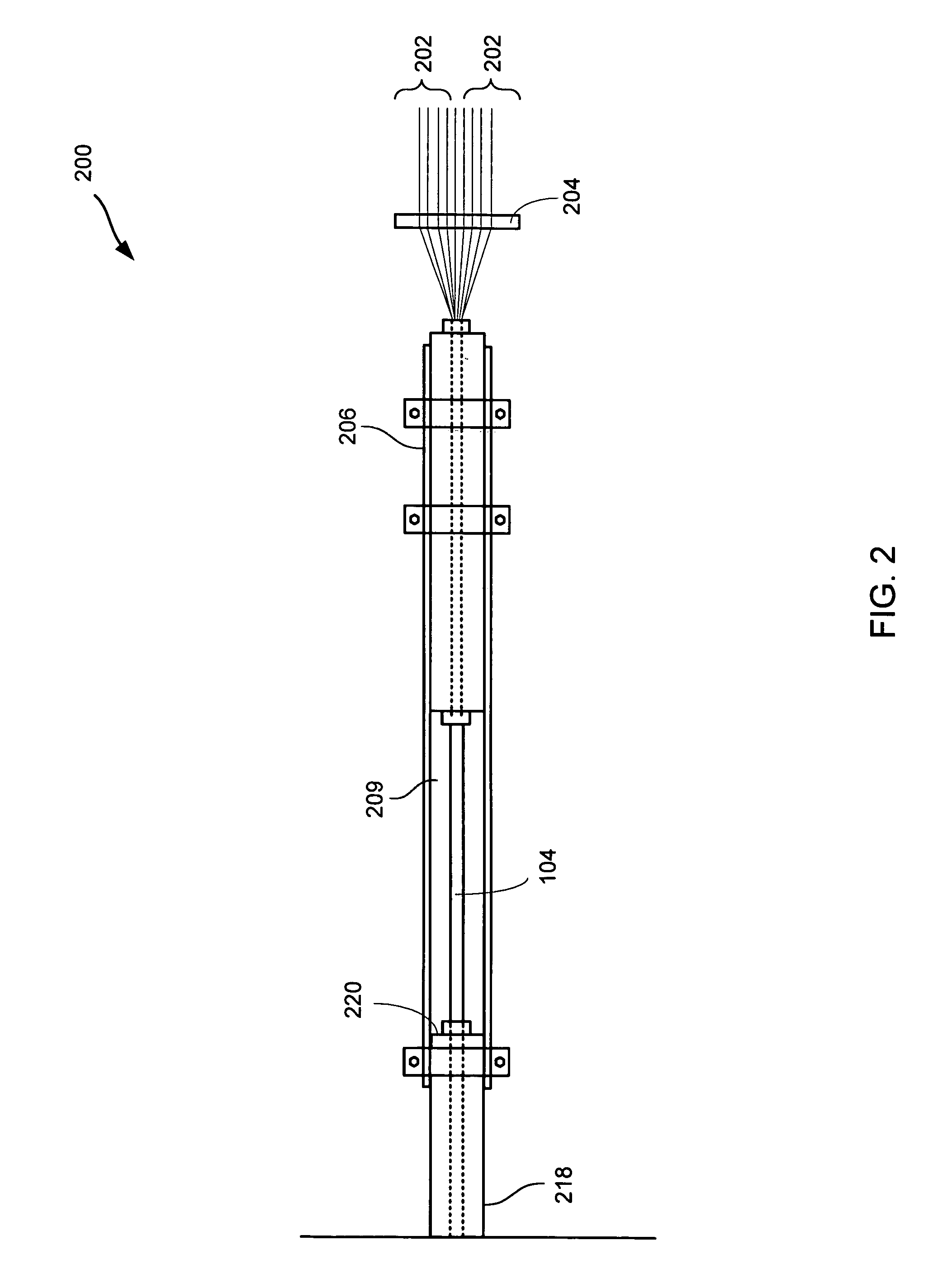
[0008] One embodiment of a composite core for an electrical transmission cable is disclosed, comprising a plurality of substantially continuous and longitudinally extending fibers embedded in a resin matrix. The fibers of the composite core are selected to meet certain inherent physical properties. Such values include, an impregnated tensile strength ranging from about 450 Ksi to about 650 Ksi; a tensile modulus of about 12 to about 16 Msi and a coefficient of thermal expansion of about 1.6×10⁻⁶ cm / cm·° C. to about 0 cm / cm·° C. Fibers comprising these values enable fabrication of an end composite core comprising a tensile strength in the range of about 250 to 350 Ksi, a modulus of elasticity of about 12 to about 16 Msi and a coefficient of thermal expansion less than or equal to about 6×10⁻⁶ cm / cm·° C. and more preferably a coefficient of thermal expansion less than or equal to about 3.6×10⁻⁶ cm / cm·° C. In this embodiment, the resin matrix comprises a catalyst activation temperature of about 200 to about 220° F. and a curing temperature ranging from about 240 to about 400° F. The composite core is further processed according to a two die processing system.

Problems solved by technology

Excessive heat will cause the cable to sag below permissible levels.
Above 100° C., ACSR cables suffer from thermal expansion and a reduction in tensile strength.
These physical changes create excessive line sag.
Although some components may have high strength and high stiffness, these components may limit other desirable characteristics of the core, for example, flexibility.
Another difficulty with high strength / high stiffness fibers is that many fiber types are expensive.
A hybridized composite core comprising two or more fibers also suffers from drawbacks resulting from inherent physical properties of the core fibers themselves.
For example, differences in the coefficient of thermal expansion for each fiber type results in a mismatch between fibers that may lead to residual stresses within the core.
The fibers are mismatched because glass is in tension while carbon is in compression.
It has been shown that degradation begins immediately and continues to propagate limiting the life span of the composite core in some cases by up to 75% of the achievable lifespan.
There are many problems associated with the design of a single fiber type composite core.
However, as noted above, a core of this type does not achieve the required flexibility for transportation.
Further, under certain conditions carbon can react with aluminum and cause corrosion of the cable.
Subsequently, the acid degrades the fibers and leads to failure of the core.
In addition, although conventional glass fibers can achieve the desired flexibility of the core, conventional glass fibers do not meet the necessary strength requirements.
The result is excessive sagging at high temperatures.

Method used


Image

  • Aluminum conductor composite core reinforced cable and method of manufacture
  • Aluminum conductor composite core reinforced cable and method of manufacture
  • Aluminum conductor composite core reinforced cable and method of manufacture

Examples


example

[0036] A particular example embodiment of the invention is now described wherein the composite strength member comprises S-2 glass. It is to be understood that the example is only one embodiment of the invention and it is not meant to limit the invention to this one embodiment. It is noted that one skilled in the art will recognize other equivalent embodiments. An example of an S-2 glass is S-2 Glass roving by AGY Corporation, the specifications of which are set forth in the brochure, “Advanced Materials—Solutions for Demanding Applications”, Pub. No. LIT-2004-341 (03 / 04), which may be found at www.agy.com, the contents of which are incorporated by reference herein. Compared to Aramid and carbon fiber, S-2 Glass fiber offers enhanced high performance properties at a lower cost. Moreover, the caternary-free, single-end roving construction of ZenTron fiber for example, translates into more efficient processing for composites that are pultruded. A typical fiber roving diameter ranges f...


PUM

PropertyMeasurementUnit
speedaaaaaaaaaa
lengthaaaaaaaaaa
lengthaaaaaaaaaa

Abstract

This invention relates to an aluminum conductor composite core reinforced cable and method of manufacture. The composite core comprises a plurality of longitudinally extending fibers embedded in a resin matrix. The composite core comprises the following characteristics: tensile strength ranging from about 250 to about 350 Ksi; a tensile modulus of elasticity ranging from about 12 to about 16 Msi; and a coefficient of thermal expansion less than or equal to about 6×10⁻⁶ cm / cm·° C. The composite core is further manufactured according to a two die pultrusion system, the system comprising tooling designed in accordance with the processing speed, selection of composite core fibers and resin and desired physical characteristics of the end composite core.

Description

[0001] This patent application is a US Continuation in Part application that claims priority to U.S. Continuation in Part application Ser. No. 10 / 971,629 filed on Oct. 22, 2004 which claims priority to U.S. Continuation in Part application Ser. No. 10 / 691,447 filed on Oct. 22, 2003 and U.S. Continuation in Part application Ser. No. 10 / 692,304 filed on 23 Oct. 2003, each of which claims priority to earlier PCT application PCT / US03 / 12520 filed in the International Receiving Office of the United States Patent and Trademark Office on 23 Apr. 2003 which claims priority from U.S. Provisional Application Ser. No. 60 / 374,879 filed in the United States Patent and Trademark Office on 23 Apr. 2002, the entire disclosure of which is incorporated by reference herein.FIELD OF THE INVENTION [0002] The present invention relates to an aluminum conductor composite core (ACCC) reinforced cable and method of manufacture. More particularly, the present invention relates to a cable for providing electric...

Claims


Application Information

Patent Timeline
Patent Type & Authority Applications(United States)
IPC IPC(8): D04H1/00
CPCB29L2031/3462B29C70/521Y10T428/249924
Inventor BRYANT, DAVIDHIEL, CLEMENT
Owner CTC GLOBAL CORP
Learn More