Energy subtraction processing method and apparatus

Inactive Publication Date: 2005-08-25
FUJIFILM CORP
View PDF5 Cites 4 Cited by
  • Summary
  • Abstract
  • Description
  • Claims
  • Application Information

AI Technical Summary

Benefits of technology

[0019] The primary object of the present invention is to provide an energy subtraction processing method, wherein adverse effects of a beam hardening phenomenon and scattering of radiation are capable of being suppressed, and an image density of an energy subtraction image obtained from energy subtraction processing is capable of being kept stable.
[0020] Another object of the present invention is to provide an energy subtraction processing method, wherein adverse effects of a beam hardening phenomenon and scattering of radiation are capable of being suppressed markedly.

Problems solved by technology

For example, in cases where quantitative determination of a bone mineral in a bone is carried out with the energy subtraction processing, even if the thickness of the bone in the object is the same, the problems described below will occur.
Specifically, if the thickness of the soft tissue surrounding the bone is large, the effects of the beam hardening phenomenon will be large, and therefore the image density of the bone pattern in the object image will become low.
If the image density of the extracted tissue pattern fluctuates due to a difference in level of effects of the beam hardening phenomenon, adverse effects will occur on the accuracy of the diagnosis, or the like.
Particularly, in cases where an energy subtraction image, which was obtained from energy subtraction processing in the past, and an energy subtraction image, which has currently been obtained from energy subtraction processing, are compared with each other, if there is a difference in level of effects of the beam hardening phenomenon between the two images, there will be the risk that a diseased part is judged by mistake as having been cured.
Further, an energy subtraction image is liable to be affected by scattering of the radiation in the object, and the image quality of the energy subtraction image changes in accordance with the degree of the radiation scattering.
Therefore, if the parameter Kc is altered independently of the other parameters, there will be the risk that the image density of the entire area of the energy subtraction image will change in accordance with the level of the beam hardening phenomenon.

Method used


Image

  • Energy subtraction processing method and apparatus
  • Energy subtraction processing method and apparatus
  • Energy subtraction processing method and apparatus

Examples


Embodiment Construction

[0068] The present invention will hereinbelow be described in further detail with reference to the accompanying drawings.

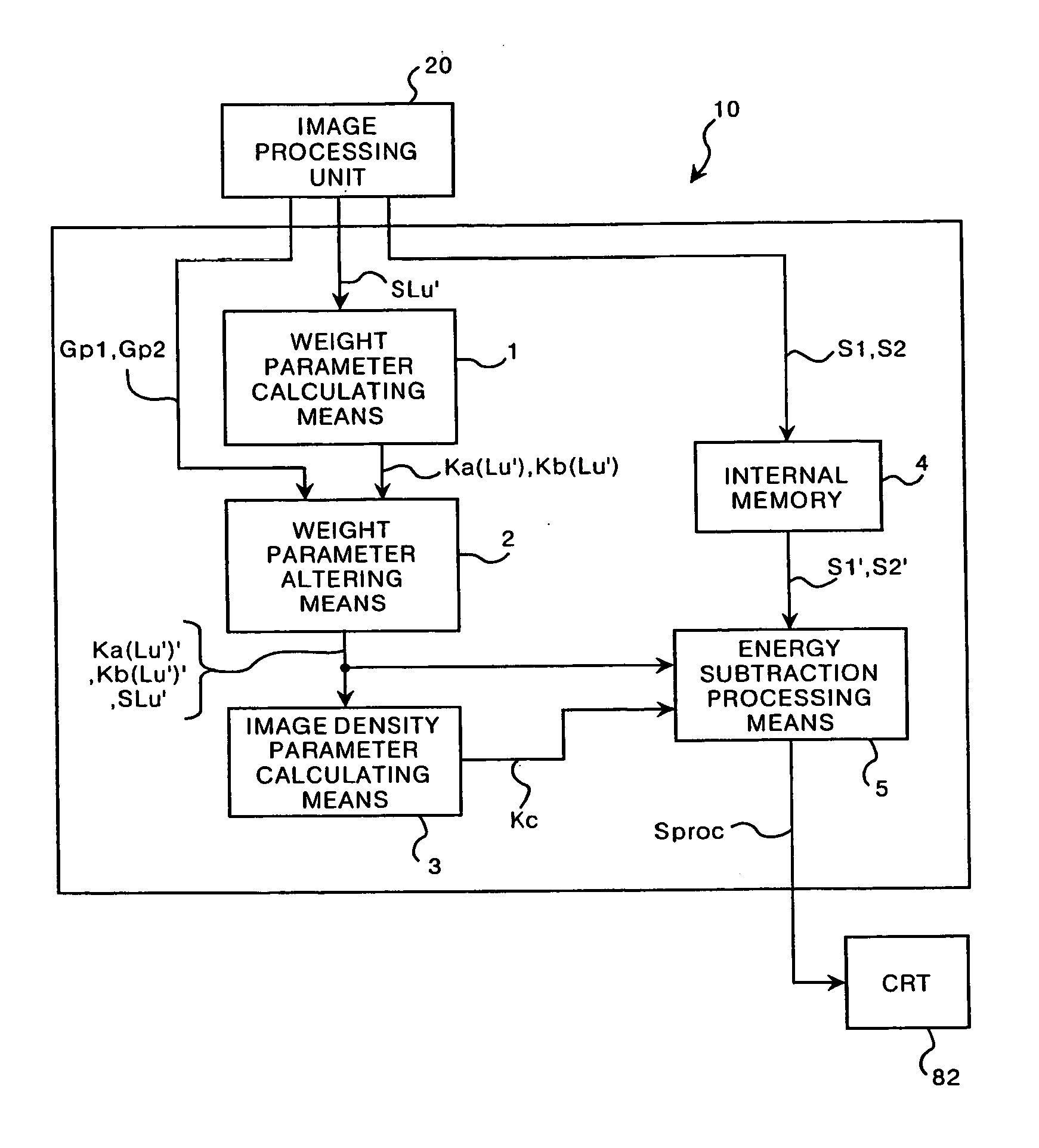
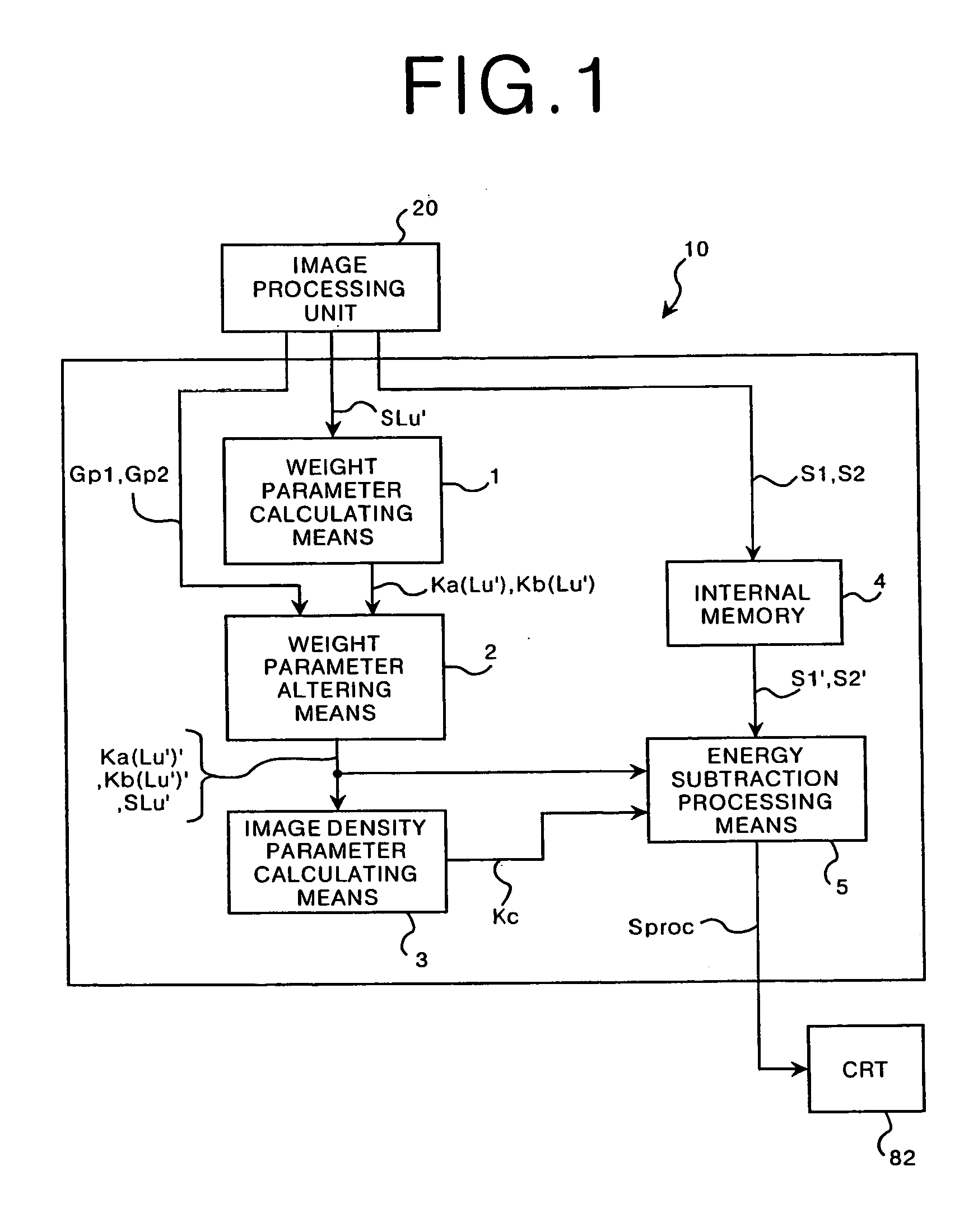
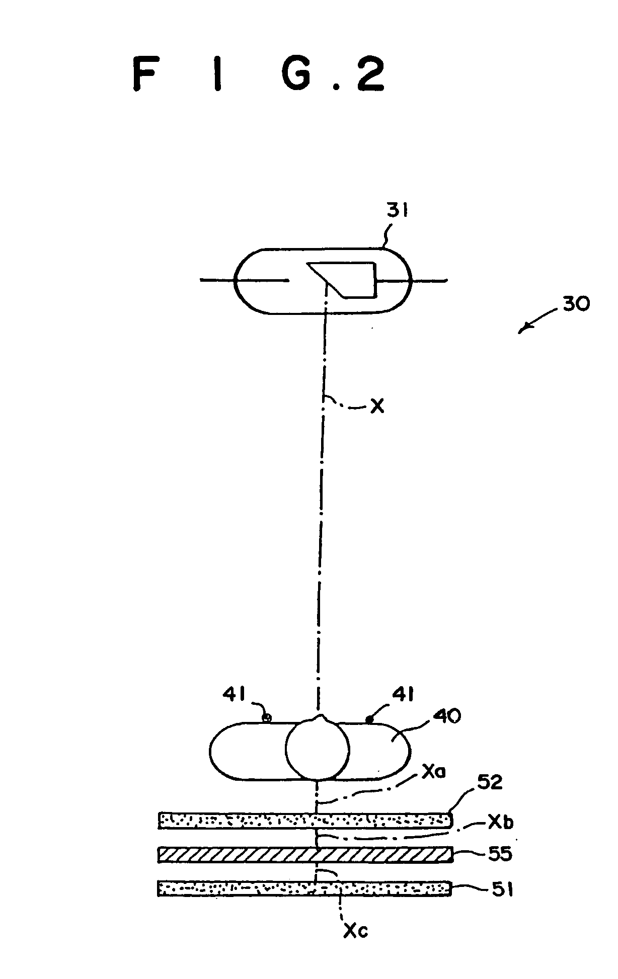
[0069]FIG. 1 is a block diagram showing an embodiment of the first energy subtraction processing apparatus in accordance with the present invention. FIG. 2 is a schematic view showing an example of a radiation image recording apparatus. FIG. 3 is a perspective view showing an example of a radiation image read-out apparatus and an image processing and displaying apparatus, which contains an image processing unit and the energy subtraction processing apparatus shown in FIG. 1.

[0070] As illustrated in FIG. 1, an energy subtraction processing apparatus 10 comprises an internal memory 4 for receiving a normalized high energy image signal S1′ and a normalized low energy image signal S2′ from an external image processing unit 20 and storing the received image signals S1′ and S2′. The normalized high energy image signal S1′ is obtained from normalization processing perf...


PUM


Abstract

Radiation image signals representing radiation images of a single object, which have been formed with several kinds of radiation having different energy distributions, are obtained. Energy subtraction processing is performed in accordance with predetermined parameters and on radiation image signal components, which represent corresponding pixels in the radiation images, and a desired tissue pattern embedded in the radiation images is thereby extracted or enhanced. A parameter, which concerns an image density shift quantity over an entire area of an energy subtraction image obtained from the energy subtraction processing, is calculated in accordance with the other parameters.

Description

BACKGROUND OF THE INVENTION [0001] 1. Field of the Invention [0002] This invention relates to an energy subtraction processing method and apparatus. This invention particularly relates to an improvement in alteration of parameters for energy subtraction processing. [0003] 2. Description of the Related Art [0004] Techniques for photoelectrically reading out a radiation image, which has been recorded on a photographic film, in order to obtain an image signal, carrying out appropriate image processing on the image signal, and then reproducing a visible image by use of the processed image signal have heretofore been known in various fields. For example, an X-ray image is recorded on an X-ray film having a small gamma value chosen according to the type of image processing to be carried out, and the X-ray image is photoelectrically read out from the X-ray film, an electric signal (i.e., an image signal) being thereby obtained. The image signal is converted into a digital image signal. The...

Claims


Application Information

Patent Timeline
IPC IPC(8): G06T5/00G06T5/50
CPCG06T5/50G06T2207/30008G06T2207/10116G06T7/0081G06T7/11
Inventor SASADA, RYOJI
Owner FUJIFILM CORP
Why Eureka
Try Eureka